Electroluminescence device, planar light source and display using the same
一种电致发光装置、致发光的技术,应用在电致发光光源、电光源、光源等方向,能够解决没有提出、没有提出EL装置、没有发现高折射率材料等问题
- Summary
- Abstract
- Description
- Claims
- Application Information
AI Technical Summary
Problems solved by technology
Method used
Image
Examples
Embodiment 1-1
[0228] 29.89 g (171.6 mM) of toluene diisocyanate (one isomer mixture: T-80, product of Mitsui Takeda Chemical Co.), 94.48 g (377.52 mM) of 4,4'-diphenylmethane diisocyanate, 64.92 g ( 308.88 mM) naphthyl diisocyanate and 184.59 g toluene were mixed in a 500 ml four-necked flask equipped with a stirrer, dropping funnel, reflux condenser and thermometer. Under stirring conditions, 8.71g (51.48mM) 1-naphthyl isocyanate and 0.82g (429mM) 3-methyl-1-phenyl-2-phospholene-2-oxide were added to the mixture, and the whole was heated to 100°C and maintained for two hours. The progress of the reaction was monitored by infrared spectroscopy. More specifically, the N-C-O stretching vibration (2,270 cm -1 ) absorption, and the N-C-N stretching vibration of carbodiimide (2,135cm -1 ) increased absorption. The reaction end point was determined by IR, and the reaction solution was cooled to room temperature to obtain a polycarbodiimide resin solution.
Embodiment 1-2
[0230] Put 89.01g (355.68mM) 4,4'-diphenylmethane diisocyanate, 24.92g (118.56mM) naphthyl diisocyanate, 44.87g (266.76mM) hexamethylene diisocyanate and 216.56g toluene in a Mix in a 500ml four-necked flask with a stirrer, dropping funnel, reflux condenser and thermometer. Add 7.52g (44.46mM) 1-naphthylisocyanate and 0.71g (3.705mM) 3-methyl-1-phenyl-2-phospholene-2-oxide to the mixture, and stir the whole at 25°C for 3 hours , and then heated to 100°C with stirring for an additional two hours. The progress of the reaction was monitored by infrared spectroscopy. More specifically, the N-C-O stretching vibration (2,270 cm -1 ) absorption, and the N-C-N stretching vibration of carbodiimide (2,135cm -1 ) increased absorption. The reaction end point was determined by IR, and the reaction solution was cooled to room temperature to obtain a polycarbodiimide resin solution.
[0231] The polycarbodiimide resins obtained from the above Synthesis Examples 1-1 and 1-2 were tested f...
Embodiment 1-3
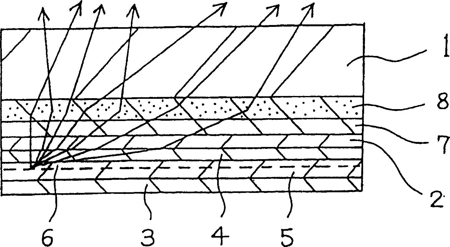
[0253] The polycarbodiimide resin solution in Synthesis Example 1-2 was used instead of the polycarbodiimide resin solution in Synthesis Example 1-1 to form a light-diffusing layer, and Example 1-1 was repeated for the rest. A dispersion obtained by dispersing fine titanium dioxide particles into the polycarbodiimide resin solution obtained in Synthesis Example 1-2 was applied to the light-diffusing layer to form a transparent layer having a thickness of 10 µm. Then repeat embodiment 1-1 to prepare such as figure 1 The organic EL device shown. The positive brightness measured by applying 15V voltage to the device is 633cd / m 2 .
[0254] The "dispersion liquid obtained by dispersing fine titanium dioxide particles" was prepared as follows. By 100 parts by weight to the ratio of 100 parts by weight of solid polycarbodiimide resin the fine TiO 2 Microparticles (products of CI Chemical, spherical particles with an average particle diameter of 30nm, dispersion in toluene solve...
PUM
 Abstract
Description
Claims
Application Information
 - R&D
- Intellectual Property
- Life Sciences
- Materials
- Tech Scout
- Unparalleled Data Quality
- Higher Quality Content
- 60% Fewer Hallucinations
Browse by: Latest US Patents, China's latest patents, Technical Efficacy Thesaurus, Application Domain, Technology Topic, Popular Technical Reports.
© 2025 PatSnap. All rights reserved.Legal|Privacy policy|Modern Slavery Act Transparency Statement|Sitemap|About US| Contact US: help@patsnap.com


