Active glass waveguide coupling microannular resonant cavity and active controller thereof

A ring resonant cavity and glass technology, which is applied in the field of integrated optics, can solve the problems of small free spectral range of devices, failure to cover C-band, large device insertion loss, etc., and achieve increased free spectral range, wide free spectral range, and small size Effect

Inactive Publication Date: 2005-07-27
SHANGHAI INST OF OPTICS & FINE MECHANICS CHINESE ACAD OF SCI
View PDF0 Cites 2 Cited by
  • Summary
  • Abstract
  • Description
  • Claims
  • Application Information

AI Technical Summary

Problems solved by technology

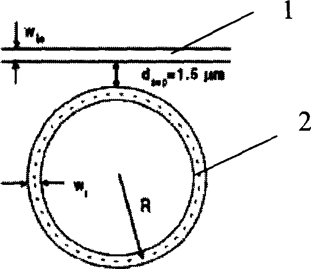
[0003] (1) The inherent high bending loss and scattering loss of the ring waveguide 2 greatly limit the size of the device, that is, the radius of curvature R of the waveguide is large, which makes the free spectral range of the device small and cannot cover the entire C-band;
[0004] (2) The insertion loss of the device is large;
[0005] (3) Although critical coupling can be achieved by controlling the coupling coefficient between waveguides 1 and 2 to achieve dynamic tunable performance of the device, the technical means used are very complicated, which is not conducive to the practical application of the device

Method used


Image

  • Active glass waveguide coupling microannular resonant cavity and active controller thereof
  • Active glass waveguide coupling microannular resonant cavity and active controller thereof
  • Active glass waveguide coupling microannular resonant cavity and active controller thereof

Examples


Embodiment Construction

[0027] The present invention will be further described below in conjunction with embodiment, but should not limit protection scope of the present invention with this.

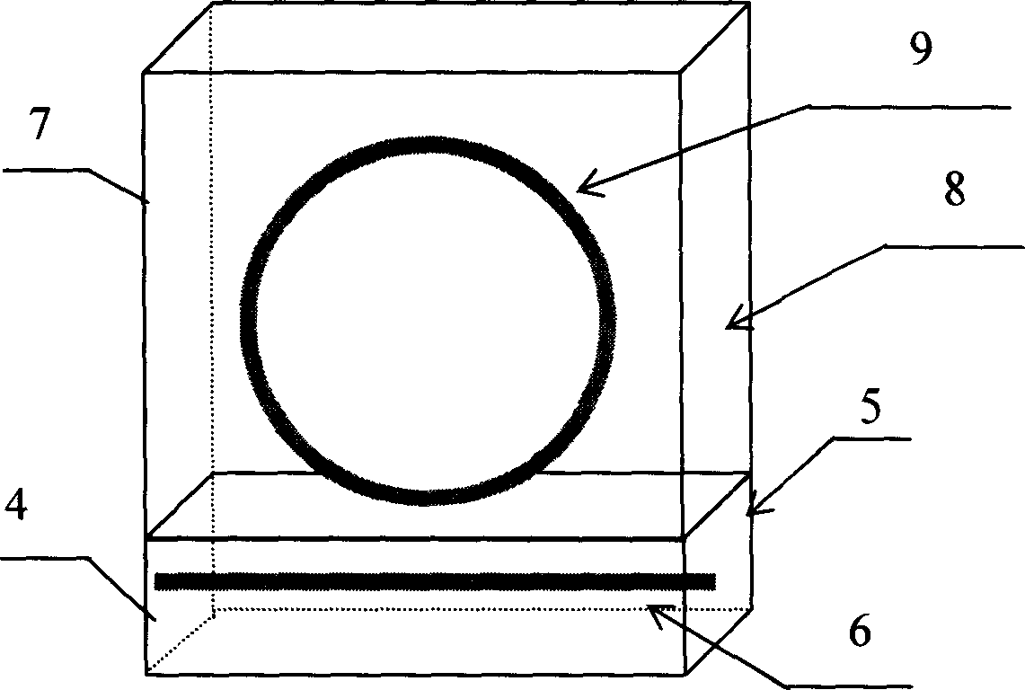
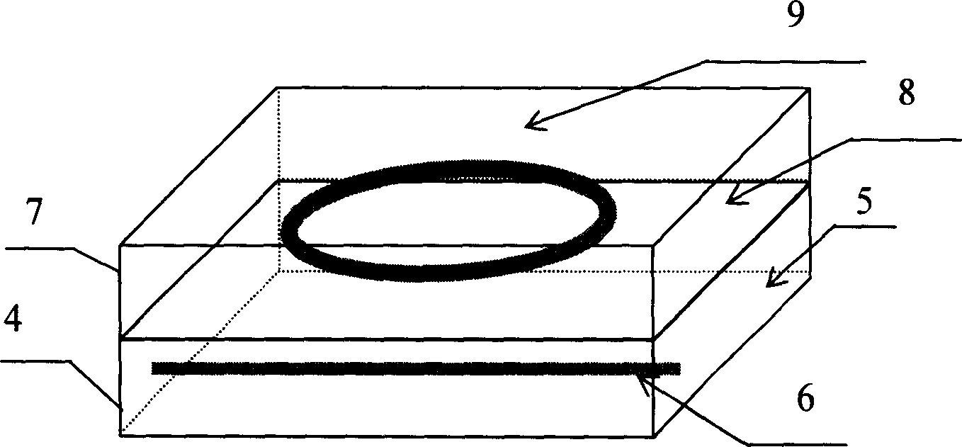
[0028] see first figure 2 with image 3 , figure 2 It is a schematic diagram of the structure of the glass active waveguide coupled micro-ring resonator bonded along the plane direction in Embodiment 1 of the present invention, image 3 : Embodiment 2 of the present invention is a schematic structural diagram of a glass active waveguide coupled micro-ring resonator bonded in the vertical direction, as can be seen from the figure, the glass active waveguide coupled micro-ring resonator of the present invention consists of a passive straight waveguide module 4 and an active The source ring waveguide module 7 is formed by bonding, and the passive straight waveguide module 4 is made of a glass matrix 5 with a certain thickness H, width W and length L and a thickness h g1 width is w g1 And the straight wavegui...


PUM


Abstract

A micro-ring resonant cavity of glass active waveguide couple is prepared by interlinking passive straight waveguide module with active ring waveguide module. The dynamic control device of it is featured as connecting a pumping laser to an input port of wavelength division complexer, using another port as signal light input port and connecting output end of the waveguide division complexer to straight waveguide.

Description

technical field [0001] The invention relates to integrated optics, in particular to a glass active waveguide coupling micro-ring resonant cavity and a dynamic control device thereof. technical background [0002] In recent years, Waveguide-Coupled Micro-Ring Resonator (WCMRR) has attracted much attention of researchers because of its broad application prospects and compact structure in optical communication systems. It can be used to build a variety of integrated photonic circuits with different functions. For example, by using its good filtering performance, it can be used to form high-performance filter devices such as dense wavelength division multiplexing filters, optical comb filters, and optical add-drop multiplexers. ; Utilizing its critical coupling (Critical Coupling) characteristics, a number of dynamically tunable integrated photonic devices can be formed, such as optical switches, modulators, dynamically configurable optical add-drop multiplexers (ROADM) and dyna...

Claims


Application Information

Patent Timeline
IPC IPC(8): G02B6/10G02B6/13G02B6/26H04B10/25
Inventor 蔡海文方祖捷陈高庭庞拂飞韩秀友
Owner SHANGHAI INST OF OPTICS & FINE MECHANICS CHINESE ACAD OF SCI
Why Eureka
Try Eureka