Floating semi-submersible oil production and storage arrangement

An oil storage, semi-submerged technology, applied in the affected field, can solve the problems of raised center of gravity, limited number of processing equipment, etc., to achieve the effect of increasing anti-overturning force and easy maintenance

Inactive Publication Date: 2005-07-27
PS COMTEK LTD
View PDF2 Cites 11 Cited by
  • Summary
  • Abstract
  • Description
  • Claims
  • Application Information

AI Technical Summary

Problems solved by technology

[0007] The second disadvantage is the limited amount of processing equipment that can be mounted on the deck as the center of gravity of the SSFP rig is raised due to the weight being added to the deck

Method used


Image

  • Floating semi-submersible oil production and storage arrangement
  • Floating semi-submersible oil production and storage arrangement
  • Floating semi-submersible oil production and storage arrangement

Examples


Embodiment Construction

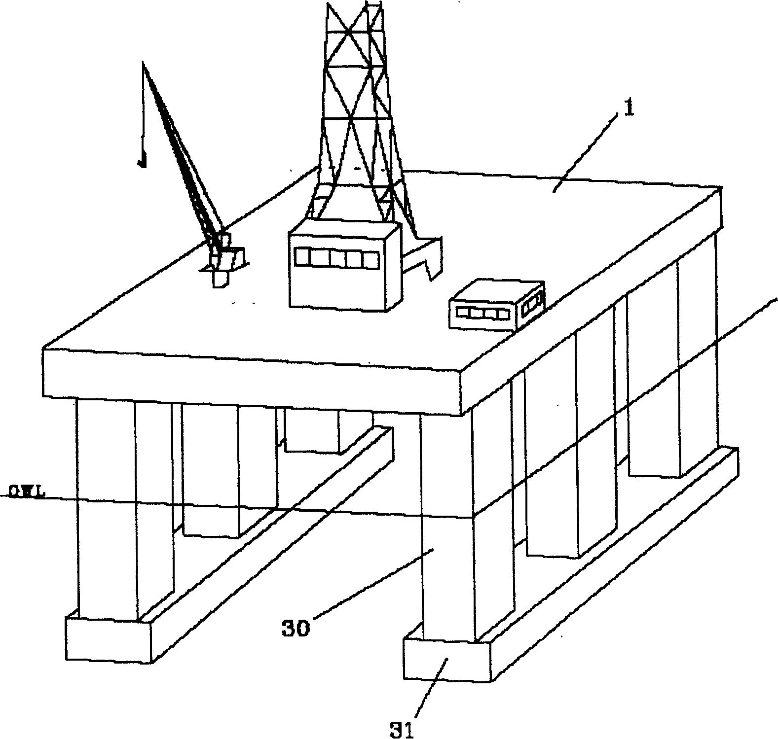
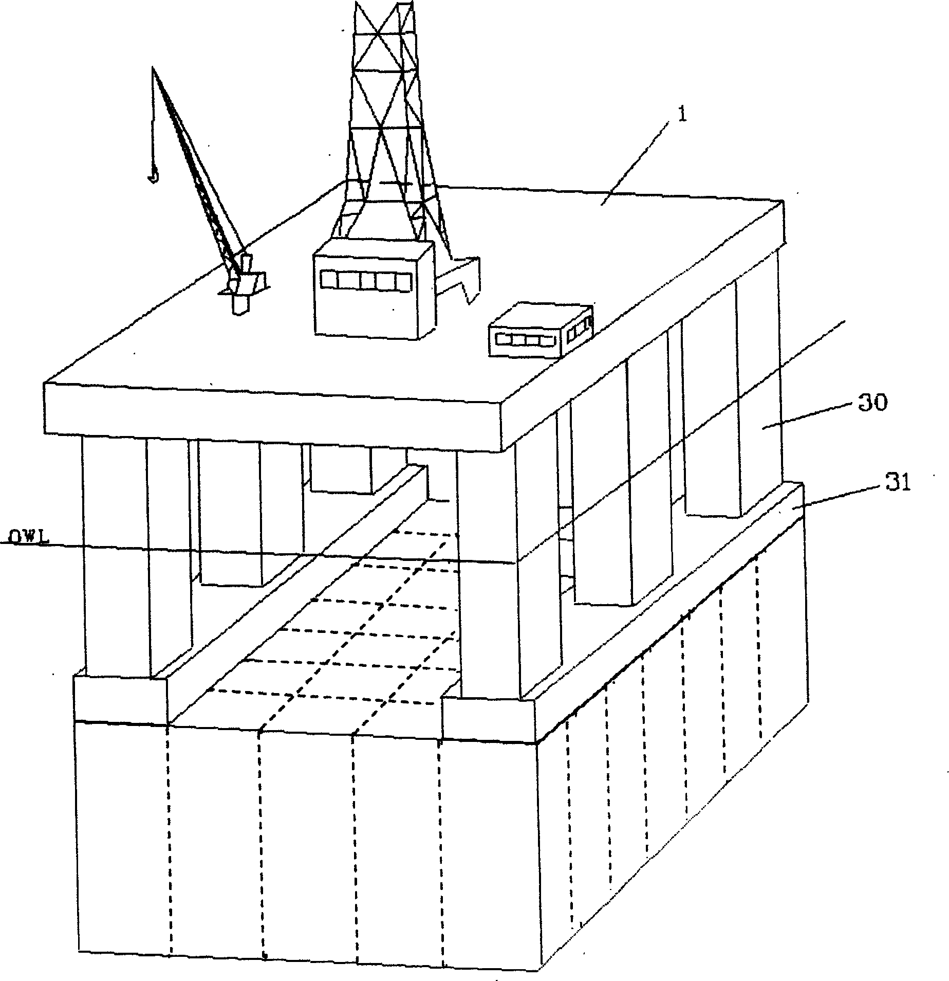
[0028] See figure 2 , the drilling rig 1 has a concrete tank 2 connected under a column 30 and a buoy 31 .

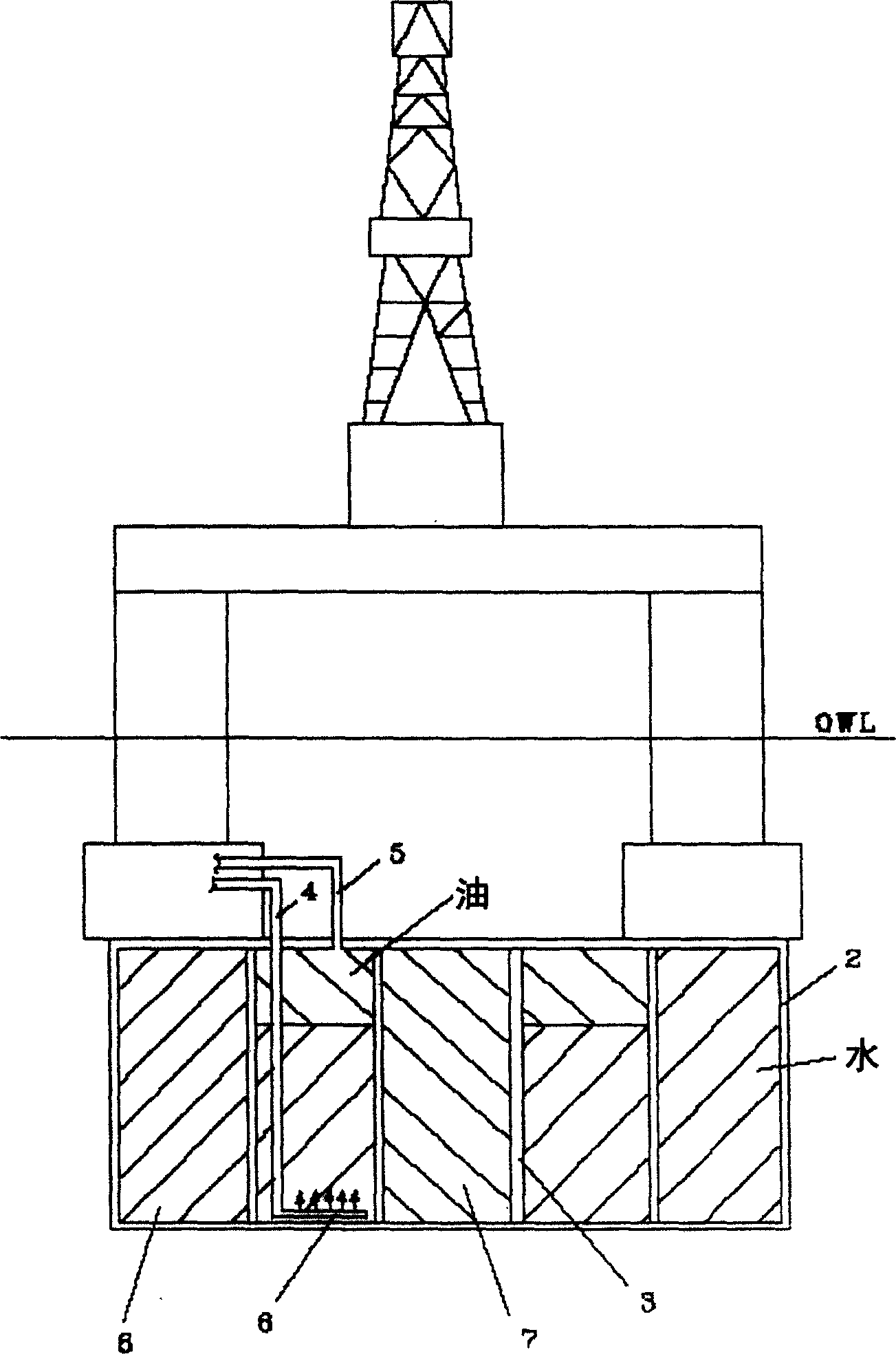
[0029] Such as image 3As shown in , the concrete boxes are separated by fluid-tight partitions in the form of inner concrete walls 3 . At least one cell in the center of the concrete box is configured to be open at the top and bottom to create a hole through the center of the concrete box whereby drilling equipment can perform drilling or well servicing operations with the box attached.

[0030] image 3 and 5 Also shown are water inlet / outlet pipes 4 and oil inlet / outlet pipes 5 of one chamber. The water pipe terminates in a diffuser tube 6 near the bottom of the chamber which minimizes mixing of oil and water as water is pumped in. The tubing terminates on the inside face of the upper surface to avoid the possibility of air bubble formation. To keep the mass of the concrete tank and contents constant when producing or unloading oil, only 4 / 5 of the chamber is ...


PUM


Abstract

An arrangement for the storage of marketable quantities of crude oil at a semi-submersible floating production vessel. The storage is achieved by hanging a segmented reinforced concrete tank (2) to the underside of the semi-submersible vessel. The semi-submersible vessel can be an existing semi-submersible drilling rig. By maintaining the mass of the tank and contents slightly greater than the displacement of the tank and by arranging the centre of gravity of the tank below its centre of buoyancy, the metacentric height of the semi-submersible vessel is approved. The storage arrangement for the oil provides the necessary maintenance of mass by either storing approximately 4/5 of the oil in oil-over-water chambers and approximately 1/5 in gas-over-oil chambers or by using a gas-over-oil-over-water arrangement in all the chambers. The piping arrangements minimize the free surface of liquids in the tank. The design ensures the internal pressure in the tank can be less than the external pressure which minimizes required reinforcement. The design provides a net positive suction head to oil export pumps located above the storage tank in a location which allows easy maintenance. The design allows all pumps, valves and instrumentation necessary for handling ballast water to be maintained within the hull of the semi-submersible where they can be easily maintained. The design allows all the valves, pumps and instrumentation necessary for handling oil to be in locations where they can be easily maintained.

Description

Background technique [0001] The oil industry often employs floating production and storage systems to develop small, remote fields. These are usually converted crude oil tankers utilizing mooring buoys tied to purpose built vessels. In order to minimize wave, tidal and wind forces acting on the tanker, the mooring is designed to allow the tanker to swing with the wind around the buoys under the influence of the resulting environmental forces. The processing equipment is installed on the deck of the drilling platform. [0002] Crude oil production from the reservoir occurs through one or more subsea wellheads through flexible flowlines from each wellhead to mooring buoys and from the buoys to the drilling platform. The system is also fitted with pipelines to carry gas and / or water from the tanker to the wellhead. Also installed are hydraulic and electrical lines from the rig to allow control of the subsea wellhead. Because the drilling platform must freely rotate around the...

Claims


Application Information

Patent Timeline
Patent Type & Authority Applications(China)
IPC IPC(8): B63B35/44
CPCB63B35/4413
Inventor 尼尔·亚历山大·科容
Owner PS COMTEK LTD
Why Eureka
Try Eureka