Laminated ceramic thermocouple and its preparing method

A technology of thermocouples and ceramics, applied in the direction of thermoelectric devices, circuits, thermometers using electric/magnetic elements that are directly sensitive to heat, etc.

Inactive Publication Date: 2005-08-10
HARBIN INST OF TECH
View PDF0 Cites 4 Cited by
  • Summary
  • Abstract
  • Description
  • Claims
  • Application Information

AI Technical Summary

Problems solved by technology

However, the interaction between the thermode material and the casing or the environment cannot be avoided at high temperatures
Therefore, thermocouple devices for measuring high temperatures need to be made of expensive precious metals or insulating materials

Method used


Image

  • Laminated ceramic thermocouple and its preparing method
  • Laminated ceramic thermocouple and its preparing method
  • Laminated ceramic thermocouple and its preparing method

Examples


specific Embodiment approach 1

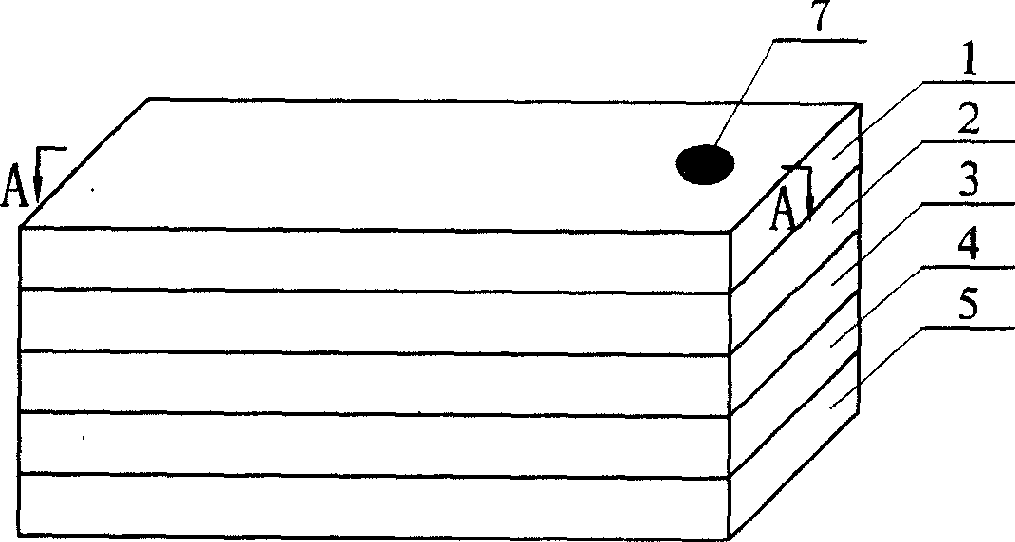
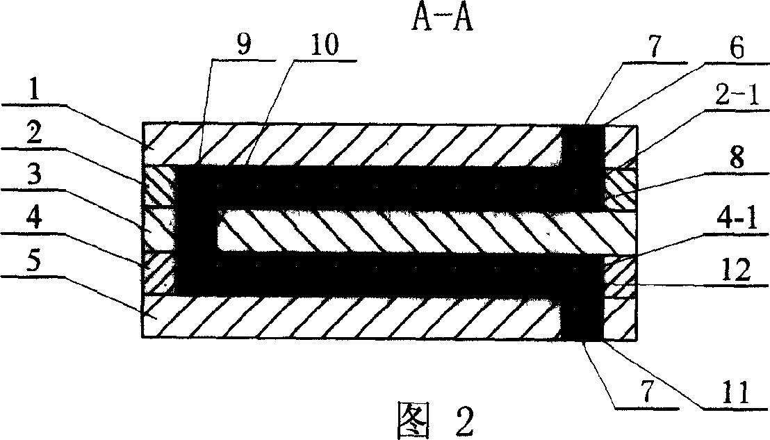
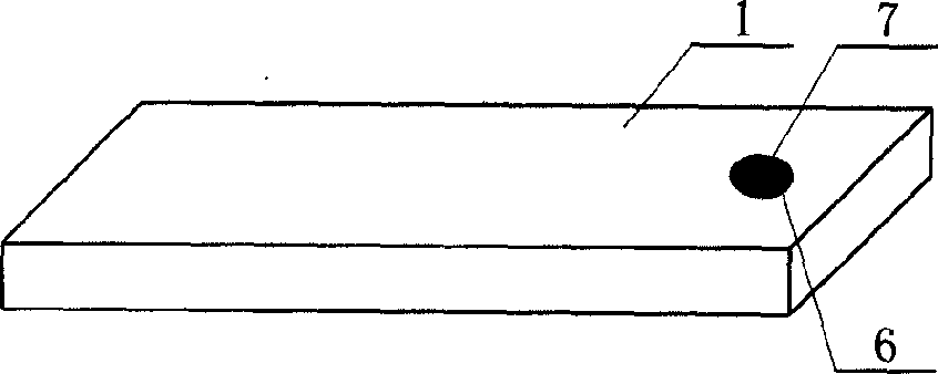
[0010] Specific implementation mode one: see Figure 1-7 , the laminated ceramic thermocouple of the present embodiment consists of an upper insulating substrate 1, a positive plate 2, a positive electrode 2-1, a middle insulating substrate 3, a negative plate 4, a negative electrode 4-1, and a lower insulating substrate 5; the upper insulating A first through hole 6 is opened between the upper end surface and the lower end surface on the right side of the substrate 1, and a conductive terminal 7 is embedded in the first through hole 6, and a third through hole 6 is opened between the upper end surface and the lower end surface on the right side of the lower insulating substrate 5. A through hole 11, a conductive terminal 7 is embedded in the third through hole 11; a first through groove 8 is opened between the upper end surface and the lower end surface of the positive plate 2, and the positive electrode 2-1 is embedded in the first through groove 8; A second through hole 10 ...

specific Embodiment approach 2

[0015] Specific embodiment two: In this embodiment, a laminated ceramic thermocouple is prepared in this way: the upper insulating substrate 1, the positive plate 2, the middle insulating substrate 3, the negative electrode plate 4, and the lower insulating substrate 5 are stacked in order from top to bottom Together, they are sintered at a sintering temperature of 1500-2500°C and a sintering pressure of 0.1-80Mpa. Since the matrix of the positive plate 2 and the negative plate 4 is the same ceramic material as the upper insulating substrate 1, the middle insulating substrate 3, and the lower insulating substrate 5, the primary problem of this embodiment is to prepare the insulating ceramic material matrix used by the thermocouple device, Utilize this base material to manufacture the ceramic blank strip with specially prefabricated through grooves 8 for mounting positive electrode 2-1, negative electrode 4-1 and through holes 6 for mounting conductive terminals 7 and conductive...

specific Embodiment approach 3

[0016] Embodiment 3: The difference between this embodiment and Embodiment 2 is that during the heating process of the billet, a reinforcing phase is formed due to the chemical reaction between the insulating matrix components and the sintering environment. In this embodiment, the material system is mainly The nitrogen oxide compound phase AlON, the compound is the prefabricated sample in the oxidizing atmosphere at 1500 ~ 1900 ° C pressureless sintering conditions according to AlN-Al 2 o 3 -Si 2 ON 2 The result of the reaction in the system. In order to increase the strength of oxynitride, β-silicon nitride with high static flexural strength is used, depending on the Si used 3 N 4 :AlN:Al 2 o 3 : Si 2 ON 2 The composition includes 0.5 to 15 vol.% silicon nitride and oxynitride phases in volume ratios ranging from 1:2:14:4 to 2:1:11:6. Thermocouples made of this material can be used up to 1400°C under oxidizing and inert conditions.


PUM

PropertyMeasurementUnit
Thicknessaaaaaaaaaa
Thicknessaaaaaaaaaa

Abstract

The thermocouple is composed of upper insulation base plate 1, positive pole plate 2 and 2-1, middle insulation base plate 3, negative pole plate 4 and 4-1, and low insulation base plate 5. A first through hole is positioned at right side of the upper insulation base plate 1, and conductive terminal is embedded in the hole. A third through hole is at right side of low insulation base plate 5, and conductive terminal is embedded in the hole. There is first through trough in plate 2, and 2-1 is embedded in the through trough. Through holes or troughs are also made up on components 3 and 4. Stacking components 1, 2, 3, 4, 5 in sequences and sintering the stacked components at 1500-2500 deg.C and 0.1-80MPa produce the thermocouple. The disclosed thermocouple is as constituent of a measuring system in use for measuring temperature in harsh environment under condition of inert or vacuum environment.

Description

Technical field: [0001] The invention relates to a thermocouple device for measuring high temperature and a preparation process of the device. Background technique: [0002] Thermocouples should meet the following conditions as a sensor for measurement: (1) stability with respect to time and temperature; (2) repeatability of thermoelectricity; (3) sensitivity to the increase of thermoelectric potential proportional to temperature; ( 4) The thermoelectric potential has a linear relationship or a simple function relationship with the temperature change; (5) It is resistant to temperature changes and thermal shocks; (6) It is resistant to the erosion of corrosive media and has good mechanical properties; (7) The preparation method is simple and easy, making different factories The products produced have the same performance. [0003] The principle of the thermoelectric device comes from the discovery of the thermoelectric effect. The essence is that two materials composed of d...

Claims


Application Information

Patent Timeline
IPC IPC(8): G01K7/02H01L35/00
Inventor 邵文柱甄良崔玉胜冯立超李义春
Owner HARBIN INST OF TECH
Why Eureka
Try Eureka