Rotary electric arc narrow gap welding method and device driven by hollow shaft motor

A hollow-shaft motor and rotating arc technology, which is applied in arc welding equipment, welding equipment, manufacturing tools, etc., can solve the problem of high spring parameter consistency and symmetry of pressing force points, shortening the service life of key components, brushes, and welding Solve problems such as large size and weight of the torch mechanism, and achieve the effects of improving work reliability and service life, improving space utilization, and improving welding quality

Active Publication Date: 2005-08-24
JIANGSU UNIV OF SCI & TECH
View PDF2 Cites 47 Cited by
  • Summary
  • Abstract
  • Description
  • Claims
  • Application Information

AI Technical Summary

Problems solved by technology

The disadvantages of this mechanism are: ①It is driven by an ordinary motor, and the movement of the conductive rod is realized by gear transmission. high
②Relying on two independent springs to make the feed plate contact with the rotating brush to realize welding power feeding, the range of pressing force is small, and the requirements for the consistency of the parameters of the two springs and the symmetry of the pressing force point are high, which may easily cause the pressing force to edge Uneven distribution in the circumferential direction shortens the service life of the key component brushes
③Only use the gas protection nozzle extending into the gap, which makes the protective effect of several welds (especially the cover weld) after multi-layer welding worse
The disadvanta

Method used


Image

  • Rotary electric arc narrow gap welding method and device driven by hollow shaft motor
  • Rotary electric arc narrow gap welding method and device driven by hollow shaft motor

Examples


Embodiment 1

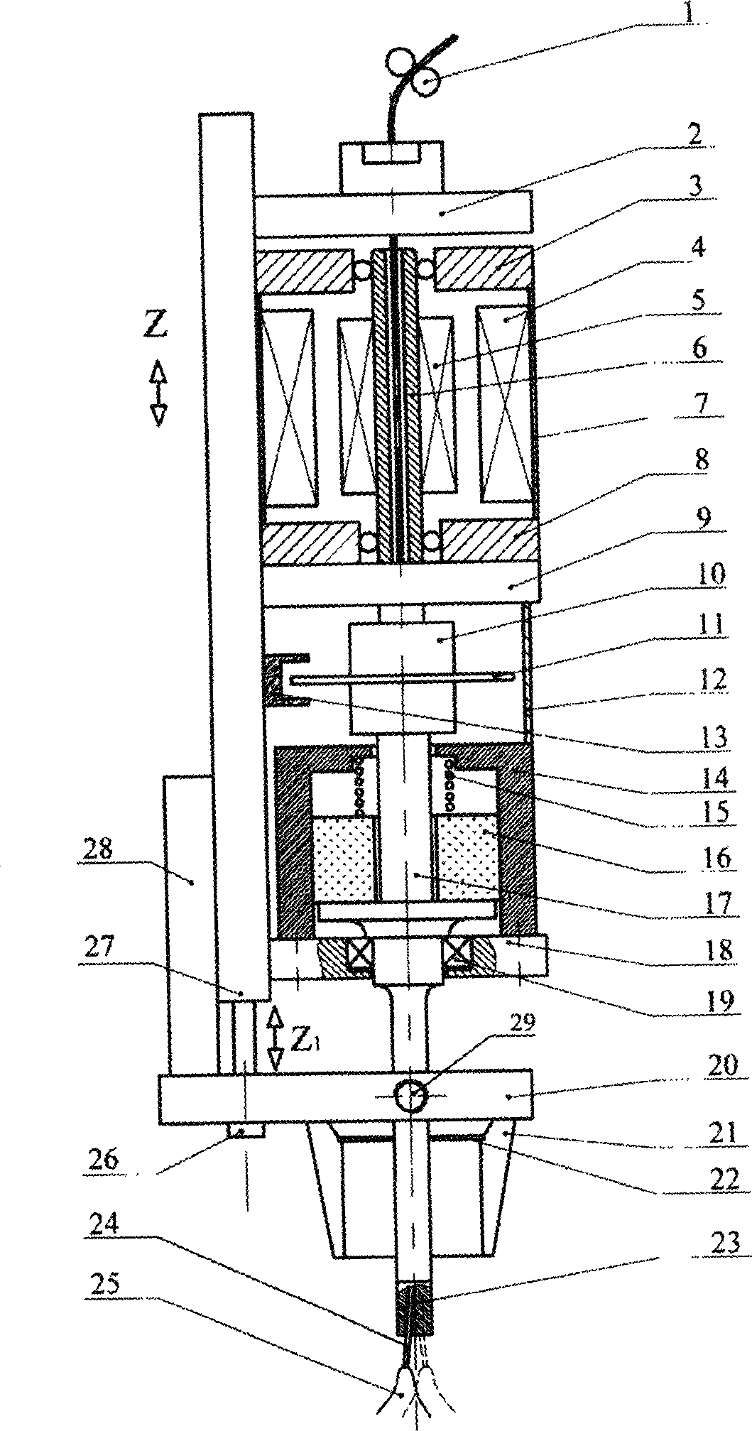
[0016] Embodiment 1 is suitable for narrow-gap welding occasions for plates below medium thickness. Depend on figure 1 It can be seen that the present invention includes a wire feed roller 1, a coupling head 2, a hollow shaft motor upper end cover 3, a motor stator 4, a motor rotor 5, a hollow shaft 6, a motor casing 7, a hollow shaft motor lower end cover 8, and a motor support 9 , coupling 10, grating 11, dust cover 12, optocoupler 13, brush cover 14, compression spring 15, brush 16, conductive rod 17, bearing seat 18, bearing 19, air guide seat 20, nozzle 21 , Gas distribution ring 22, conductive tip 23, welding wire 24, welding arc 25, screw 26, support plate 27, guide rail 28, gas inlet 29, etc.

[0017] like figure 1 As shown, the welding wire 24 sent by the wire feeding roller 1 penetrates through the central hole of the coupling head 2, passes through the hollow shaft 6 of the motor, the coupling 10, and the central hole of the conductive rod 17, and is sent out from...

Embodiment 2

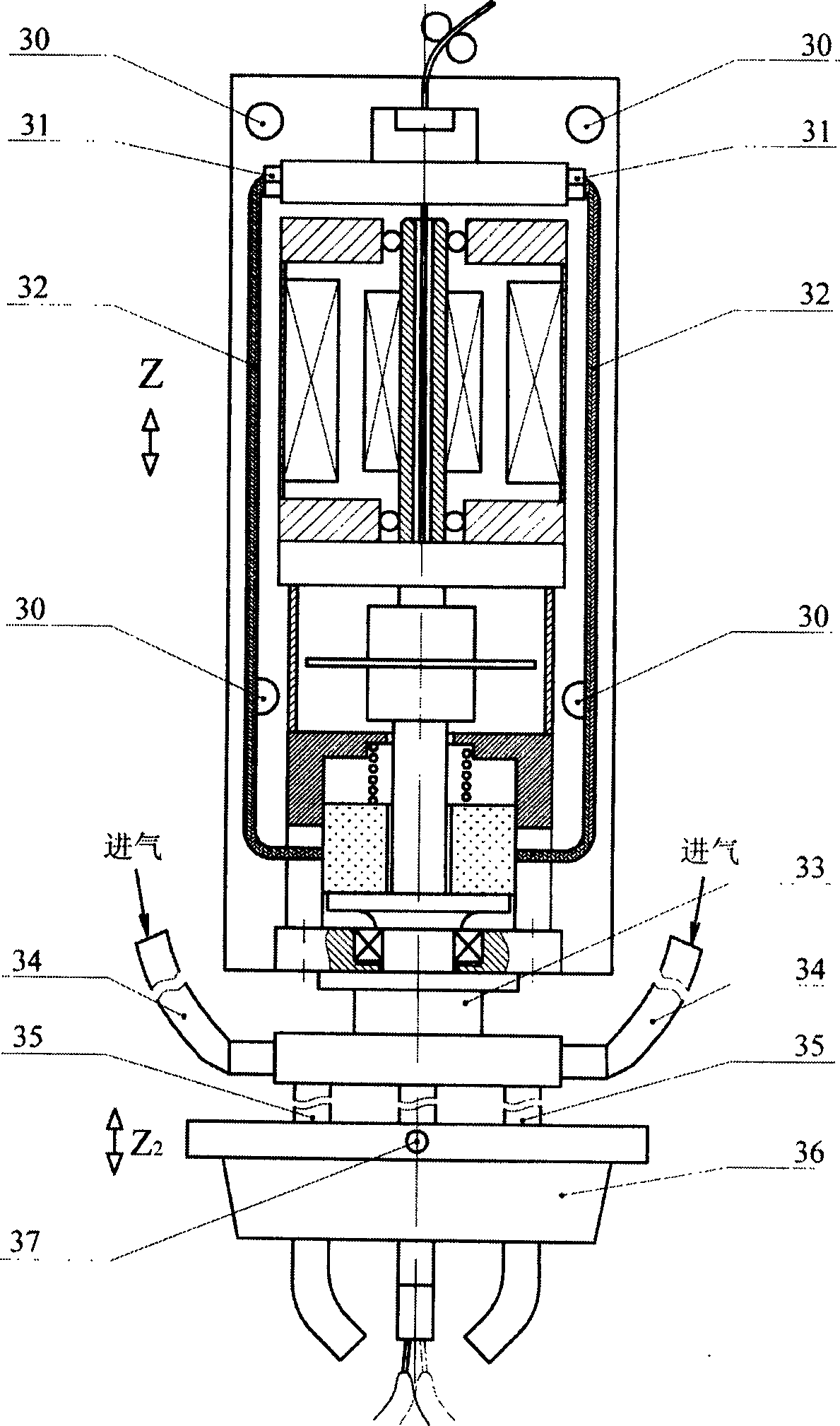
[0020]Embodiment 2 is suitable for narrow gap welding occasions of large thickness plates. Compared with Embodiment 1, the air guide seat 20, nozzle 21, gas distribution ring 22, screw rod 26 and guide rail 28 are removed, and the nozzle holder 33, flat nozzle 35 and box nozzle 36 are added, and the remaining parts are the same as Embodiment 1. The upper end of the nozzle holder 33 is fixedly connected with the bearing seat 18 or the support plate 27, and the lower end is fixedly connected with two symmetrically arranged flat nozzles 35. The box-shaped nozzle 36 is connected with another independent nozzle height adjustment device, and can move along the Z2 direction to maintain a proper distance between the box-shaped nozzle 36 and the surface of the workpiece. The main purpose of setting the box-shaped nozzle is to enhance the protective effect of the last few welds when welding large and thick plates. The flat nozzle 35 moves through the box nozzle 36 and extends into the ...

Embodiment 3

[0022] Embodiment 3 Compared with Embodiment 1, the screw rod 26 and the guide rail 28 are removed, and the air guide seat 20 is connected with another independent nozzle height adjustment device to realize the independent adjustment of the distance from the nozzle 21 to the surface of the workpiece, and the rest are the same as in the embodiment 1. In this way, during continuous and fully automatic multi-layer narrow-gap welding, there is no need to fine-tune the height of the nozzle 21 after each layer of welding is completed, which improves the degree of automation.


PUM


Abstract

A welding machine for welding in narrow gap by rotary arc is composed of a connector of welding electric cable, an electric motor unit with hollow shaft for feeding welding wire through it, an electric feeding unit of brush with close slide matching with the flange of electric conducting rod, a spray unit with eccentrical hole for generating the rotary arc at the front end of welding wire, and speed measuring unit consisting of raster and light coupler. Its straight nozzle can be inserted in the narrow gap to be welded.

Description

technical field [0001] The invention relates to the field of welding technology, in particular to a rotary arc narrow gap welding method and device driven by a hollow shaft motor. Background technique [0002] Rotary arc narrow gap welding is a new type of narrow gap welding method. It uses a mechanical method to rotate the conductive rod of the torch around its own axis to drive the arc that passes through the end of the welding wire from the eccentric conductive tip to perform a rotary scanning movement, thereby obtaining uniform welding. Stable sidewall penetration. The rotating arc process can also be used in non-narrow gap arc welding occasions to obtain excellent weld shape. The welding torch is the key mechanism to realize the rotary arc welding process. [0003] The narrow-gap welding torch in the existing high-speed rotary arc welding equipment, Japanese Patent Laid-Open No. 58-176073, realizes the movement of the conductive rod through a pair of gear transmission...

Claims


Application Information

Patent Timeline
IPC IPC(8): B23K9/022B23K9/10B23K9/12
Inventor 王加友杨峰国宏斌
Owner JIANGSU UNIV OF SCI & TECH
Why Eureka
Try Eureka