Push and pull cylinder variable frequency energy-saving hydraulic elevator system of balancing load by accumulator loop

A technology for balancing loads and elevator systems, applied to elevators in buildings, energy efficiency of elevators, sustainable buildings, etc., can solve problems such as reducing installed power, increasing flow, increasing manufacturing costs and installation space, and achieving reduction Installed power and energy consumption, reduction of installation and manufacturing costs, effects of size and weight reduction

A technology for balancing loads and elevator systems, applied to elevators in buildings, energy efficiency of elevators, sustainable buildings, etc., can solve problems such as reducing installed power, increasing flow, increasing manufacturing costs and installation space, and achieving reduction Installed power and energy consumption, reduction of installation and manufacturing costs, effects of size and weight reduction

CN1657393AInactive Publication Date: 2005-08-24ZHEJIANG UNIV

Image

  • Push and pull cylinder variable frequency energy-saving hydraulic elevator system of balancing load by accumulator loop

Examples


Embodiment Construction

[0012] The present invention will be further described below in conjunction with drawings and embodiments.

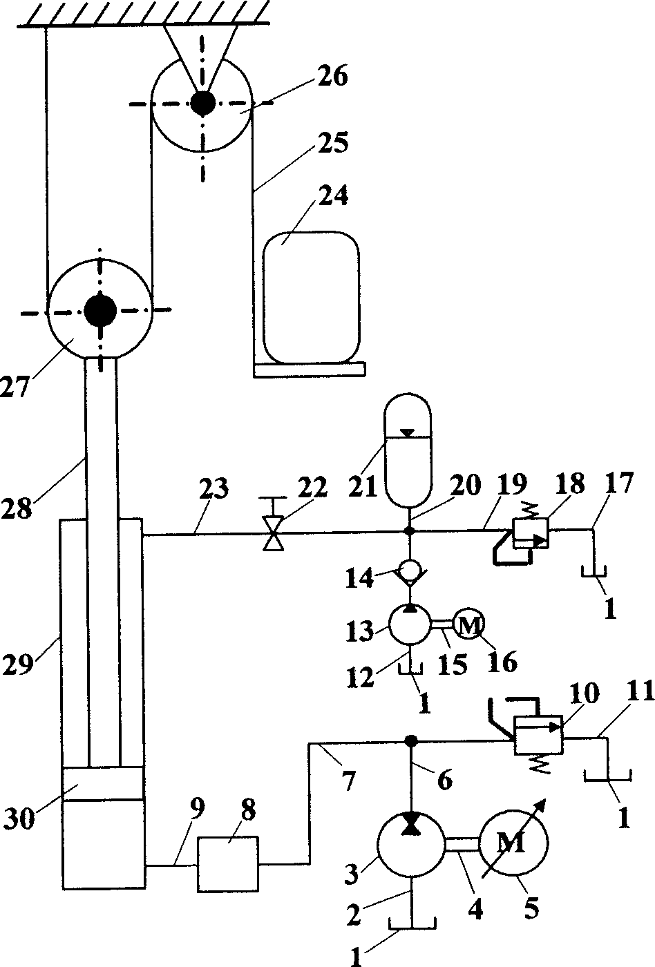
[0013] As shown in the accompanying drawings, the present invention includes a mechanical system and a hydraulic control system that are connected to the piston rod 28 of the elevator car 24 through a steel rope 25, a fixed pulley 26, a movable pulley 27 and a hydraulic cylinder 29, and a hydraulic control system; the hydraulic control system includes :

[0014] 1) Main hydraulic circuit system: The vector frequency conversion motor 5 is connected to the two-way hydraulic pump 3 through the first coupling 4, one end of the two-way hydraulic pump 3 is connected to the oil tank 1 through the pipeline 2, and the other end is respectively connected to the hydraulic control valve through the pipelines 6 and 7 One end of 8 is connected to one end of safety valve 10 through pipeline 6, the other end of safety valve 10 is connected to fuel tank 1 through pipeline 11, and the ot...


PUM


Abstract

An energy-saving hydraulic elevator system is composed of a mechanical system, a master hydraulic loop with vectorial frequency-varying volume control to regulate the rotation speed of motor, and an energy accumulator loop system for balancing the most of the weight of cage system. Said energy accumulator loop can absorb energy when cage is moving down or release energy when cage is moving up.

Description

technical field [0001] The invention relates to a control system of an elevator, in particular to a push-pull cylinder frequency conversion energy-saving hydraulic elevator system adopting an accumulator circuit to balance loads. Background technique [0002] Hydraulic elevators have the advantages of no need for a top-floor machine room, large load capacity, stable and comfortable operation, high safety and reliability, making them cheaper and easier to debug and maintain than traction elevators of the same specification. Therefore, in recent decades, hydraulic elevators have been widely promoted and applied in various countries. [0003] Because the general hydraulic elevator does not have a counterweight, the elevator completely relies on the power system to do work when it goes up, unlike the traction elevator that can rely on the counterweight to provide part of the power, and the efficiency of the hydraulic power system is not high, so the installed capacity of the hyd...

Claims


Application Information

Patent Timeline
24 Aug 2005
Publication
CN1657393A
IPC
B66B1/04; B66B11/04
CPC
Y02B50/148; Y02B50/146; Y02B50/00
Inventors
徐兵; 黄方平