Cooling system for electronic apparatus, and electronic apparatus using the same

A technology of electronic equipment and cooling system, which is applied in the field of electronic equipment, and can solve the problems of decreased cooling efficiency of heating elements, insufficient heat generation, and inability to make full use of heat-absorbing cooling capacity, etc., and achieve the effect of increasing the transfer area and improving the cooling efficiency

Inactive Publication Date: 2005-08-24
HITACHI LTD
View PDF8 Cites 21 Cited by
  • Summary
  • Abstract
  • Description
  • Claims
  • Application Information

AI Technical Summary

Problems solved by technology

[0016] In such a case where the area of ​​the CPU as a heat generating element in contact with the heat-absorbing (cooling) jacket is very small, the heat generated in the CPU diffuses to the contact surface with the above-mentioned heat-absorbing (cooling) jacket and its peripheral portion, and then transfers to the heat-absorbing (cooling) jacket. The liquid refrigerant flowing in the jacket is discharged to the outside, but when the contact area is small, even if the heat is discharged to the periphery to some extent, it does not spread to the whole jacket. Therefore, the heat-absorbing (cooling) jacket is Decreased cooling efficiency of heating elements
That is, at a position far away from the contact position with the CPU, the transfer of heat to the liquid refrigerant flowing in the jacket cannot be sufficiently performed. Therefore, the cooling capacity of the heat-absorbing (cooling) jacket cannot be fully utilized, and only its Part of ability

Method used


Image

  • Cooling system for electronic apparatus, and electronic apparatus using the same
  • Cooling system for electronic apparatus, and electronic apparatus using the same
  • Cooling system for electronic apparatus, and electronic apparatus using the same

Examples


Embodiment Construction

[0045] Hereinafter, embodiments of the present invention will be described in detail with reference to the drawings.

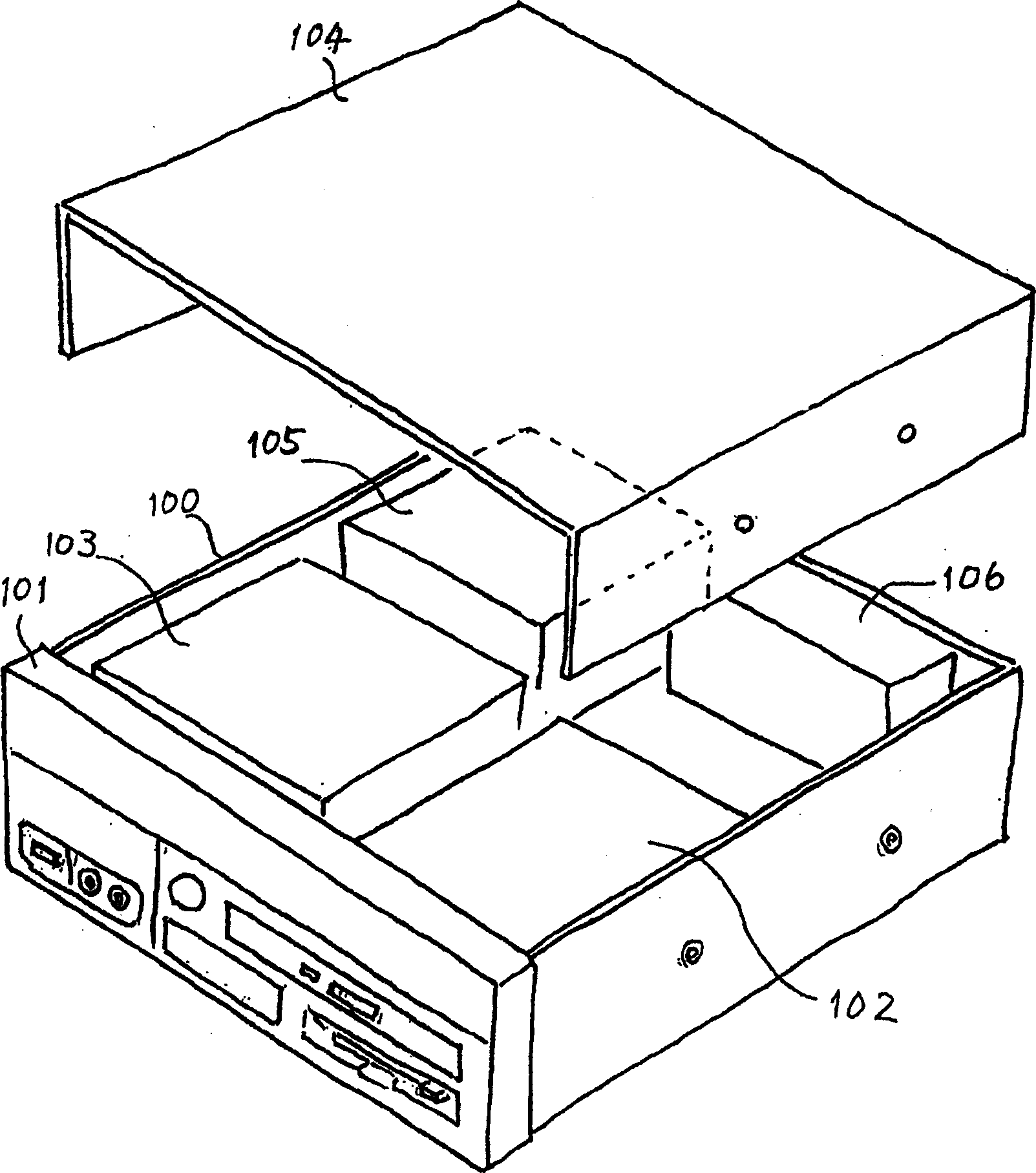
[0046] first, figure 2 An example of the overall configuration of an electronic device having a liquid cooling system according to an embodiment of the present invention is shown. In this example, for example, a case where the present invention is applied to the main body of a desktop personal computer is shown.

[0047] First, as shown in the figure, the main body of a desktop personal computer has a box 100 formed of a metal plate in a cubic shape, for example, and various switches including a power switch, connection terminals, indicator lights, etc. are provided on the front panel 101. , In addition, a drive device 102 for driving various external information recording media such as floppy disks, CDs, and DVDs is arranged inside and opened toward the above-mentioned front panel portion 101 . In addition, reference numeral 103 in the figure shows a stora...


PUM


Abstract

An electronic apparatus, such as, personal computers of so-called a desktop type and a notebook type, as well as, a server, etc., having a cooling system being high in cooling efficiency, wherein a CPU 200 in need of cooling is installed within a hosing 100, and the liquid cooling system for cooling the CPU, comprises: a heat-receiving (cooling) jacket 50; a radiator 60; and a circulation pump 70, wherein the heat-receiving (cooling) jacket 50, for transmitting heat generated from a heat-generation element, i.e., the CPU, into a liquid coolant flowing with in an inside thereof, has a heat diffusion plate 90 attached on the lower surface thereof. This heat diffusion plate encloses an operating fluid 94, such as water, within a space, which is hermetically sealed and formed within an inside thereof, and also has heater elements 95, being provided in contact with a portion the operating fluid. To those heater elements 95 are supplied a pulse-like electric power. With this, a portion of the operating fluid repeats forming / extinguishing, to give vibration to the operating fluid, thereby diffusing the heat over the entire of the diffusion plate, as a whole, thereafter the heat is transmitted to the heat-receiving (cooling) jacket. Or, alternatively, it may be connected with a heat radiation fin 300.

Description

technical field [0001] The present invention relates to electronic equipment such as desktop or notebook personal computers or servers, and more particularly to a cooling system for electronic equipment capable of efficiently cooling semiconductor integrated circuit elements mounted therein as heat-generating elements, and methods using the same. Electronic equipment. Background technique [0002] Semiconductor integrated circuit elements as heat generating elements in electronic equipment such as desktop or notebook personal computers or servers, especially heat generating elements represented by CPU (Central Processing Unit) usually need to be cooled in order to ensure their normal operation. For this reason, conventionally, the cooling has been realized by using a heat transfer body integrally formed with fins called fins and a fan for blowing cooling air thereto. However, in recent years, the continuous miniaturization and high integration of semiconductor integrated ci...

Claims


Application Information

Patent Timeline
Patent Type & Authority Applications(China)
IPC IPC(8): H05K7/20F28D15/02F28D15/06F28F7/00F28F13/10G06F1/20H01L23/34H01L23/36H01L23/473
CPCH01L2924/0002F28D15/06H01L23/473F28F13/10F28D15/0233G06F1/20G06F2200/201H05K7/20809H01L23/345H01L2924/00B29C51/145B29C51/262B29C51/38B29K2067/003B29K2075/00B29K2105/0854B29L2009/00B29L2031/3005
Inventor 铃木敦
Owner HITACHI LTD
Why Eureka
Try Eureka