
Method for monitoring petroleum reservoir performance by using biomarkers

A dynamic monitoring and biomarker technology, applied in measuring devices, earthwork drilling, special data processing applications, etc., can solve problems such as low accuracy of test data, high cost of underground operations, and long construction period

Inactive Publication Date: 2005-09-07
LIAOHE GASOLINEEUM EXPLORATION BUREAU
View PDF0 Cites 15 Cited by
  • Summary
  • Abstract
  • Description
  • Claims
  • Application Information

AI Technical Summary

Problems solved by technology

In the current technology, the pipe string test method, annular space test method, gas lift method, water finding flowmeter, radioactive tracer method, etc. are mainly used. The main disadvantage of the above methods is that the oil well must be shut down when used for monitoring, and the normal production of the oil well must be stopped. In addition, the cost of downhole operation is too high, and the construction period is long, the accuracy of test data is low, and it is difficult to truly achieve the purpose of dynamic monitoring of oil wells. In addition, for self-injection oil wells, it is only possible to carry out oil wells with eccentric wellheads. Annulus testing is used to understand the oil production of each single layer in the oil well and its contribution to the single well. Therefore, there are many unsatisfactory aspects of using the above method
A bio-reservoir dynamic monitoring method that breaks through the traditional method of obtaining the contribution rate of a single layer of oil and water wells to an oil well by using a test method. This method can replace the above-mentioned various test methods and technologies. This method has not been found in domestic and foreign patents after searching report

Method used


Image

  • Method for monitoring petroleum reservoir performance by using biomarkers
  • Method for monitoring petroleum reservoir performance by using biomarkers
  • Method for monitoring petroleum reservoir performance by using biomarkers

Examples


Embodiment 1

[0016] 1. Sampling (sampling of each single layer of Jin 16-19-411#).

[0017] serial number

[0018] When sampling, the wellhead oil sample was 1000 ml, and the 1-8 layers in the well were all perforated well wall core rock samples, and the sample weight of each layer was 1 gram.

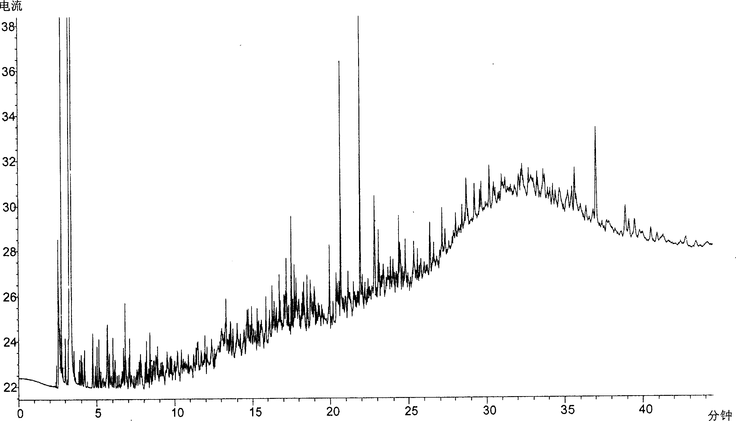
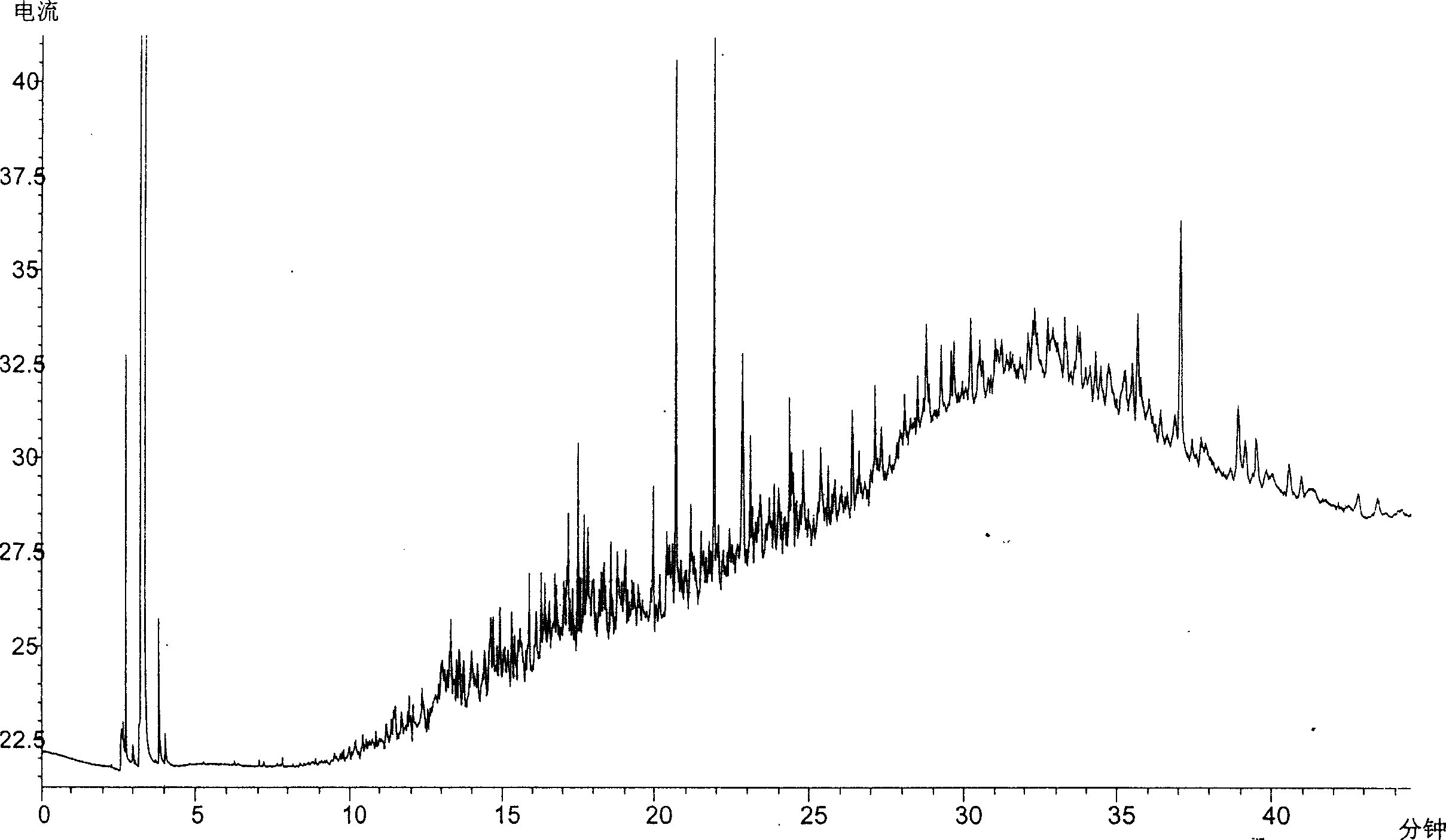
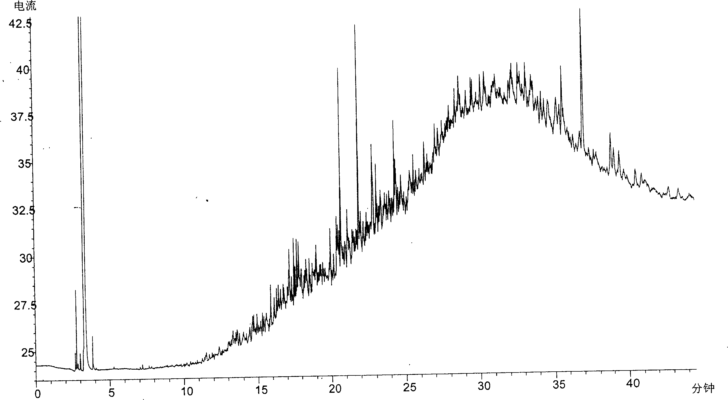
[0019] 2. Align each single layer 2 to 8 according to the sequence number of the rock layer. After quantitative immersion and displacement of layer samples, GC-6890N gas chromatograph was used for gas chromatographic analysis (Fig. Hydrocarbon components, colloids and asphaltenes, and then select the chromatographic fingerprint parameters from them.

[0020] 3. After selecting the crude oil chromatographic fingerprint parameters according to the gas chromatographic analysis results, the hydrocarbon component value in each single-layer chromatographic analysis data, that is, hundreds of small peaks on the gas chromatogram (in Figures 1 to 8), represented by a certain The effective finger...

Embodiment 2

[0026] The present invention adopts the GC-6890N gas chromatograph when analyzing the oil sample by using the gas chromatograph analyzer.

[0027] The crude oil chromatographic fingerprint refers to a small peak that can be identified on the crude oil gas chromatogram after gas chromatographic analysis. The peaks of those wellhead crude oil fingerprint peaks are not in the range of all monolayer peaks, and those fingerprint peaks are removed. The specific selection criteria are: peak slope: 10, peak width: 0.04, area limit: 1, peak height limit: 1.


PUM


Abstract

The invention discloses a method of dynamically monitoring the oil deposit using the biomarker, which belongs to the field of dynamically monitoring oil deposit technique. Said invention adopts the high water-cut well aiming at multiple-zone mixing production, analyzes the oil sample in the mine pore and hydrocarbon compound of the single layer core barrel sample, inputs the color spectrum finger-print parameter to the program in the computer for measuring the contribution ratio of oil and water single-zone well to the crude oil, and we can plug the oil-water layer of no use or take adjusting steps according to the data.

Description

Technical field: [0001] The invention relates to a method for dynamic monitoring of oil reservoirs with biomarker compounds, which belongs to the technical field of dynamic monitoring of oil reservoirs. Background technique: [0002] Reservoir dynamic monitoring is a main method used to adjust the oilfield development plan in the process of oilfield development. According to the dynamic changes of oilfield oil wells, that is, oil production and water production, the production status of oil wells is monitored in a timely manner. The purpose of monitoring is to grasp Water production and oil content of each single layer in the oil and water wells, so as to block the water layers with high water content and no oil in the well, so that the various layers in the oil and water wells can exert their potential. In the current technology, the pipe string test method, annular space test method, gas lift method, water finding flowmeter, radioactive tracer method, etc. are mainly used....

Claims


Application Information

Patent Timeline
IPC IPC(8): E21B49/08G01N30/02G06F19/00
Inventor 高大岭许宪金贾耀惠刘火祥宋明会宋超李小娟苑宏瑞
Owner LIAOHE GASOLINEEUM EXPLORATION BUREAU
Learn More