
Capacitively coupled plasma reactor with magnetic plasma control

A plasma and reactor technology, which is applied in plasma, ion beam tube, semiconductor/solid-state device manufacturing, etc., can solve problems such as magnetic field strength limitation, reaction chamber or wafer arc discharge problems, etc.

Inactive Publication Date: 2005-09-14
APPLIED MATERIALS INC
View PDF1 Cites 15 Cited by
  • Summary
  • Abstract
  • Description
  • Claims
  • Application Information

AI Technical Summary

Problems solved by technology

Due to the sharp switching of the CMF magnetic field, this method is prone to arcing problems in the reaction chamber or wafer, so the magnetic field strength must be limited
As a result, in some applications the magnetic field is insufficient to compensate for ion density inhomogeneities of the plasma generated by the reaction chamber

Method used


Image

  • Capacitively coupled plasma reactor with magnetic plasma control
  • Capacitively coupled plasma reactor with magnetic plasma control
  • Capacitively coupled plasma reactor with magnetic plasma control

Examples


Embodiment Construction

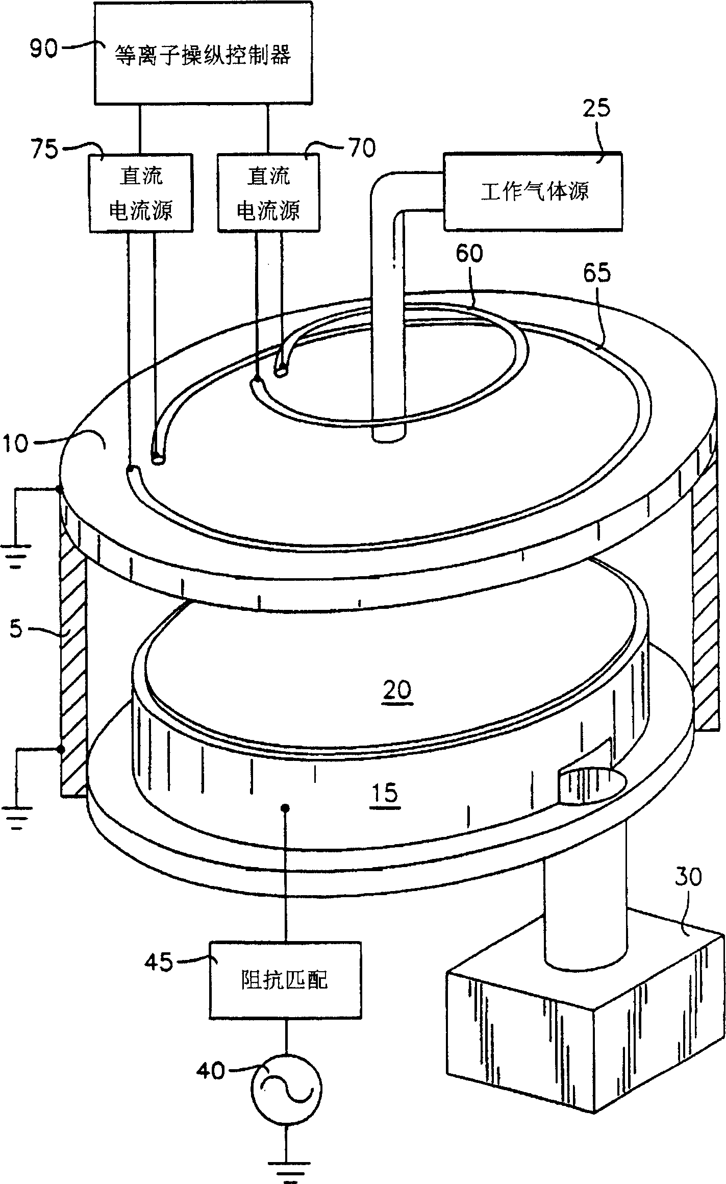
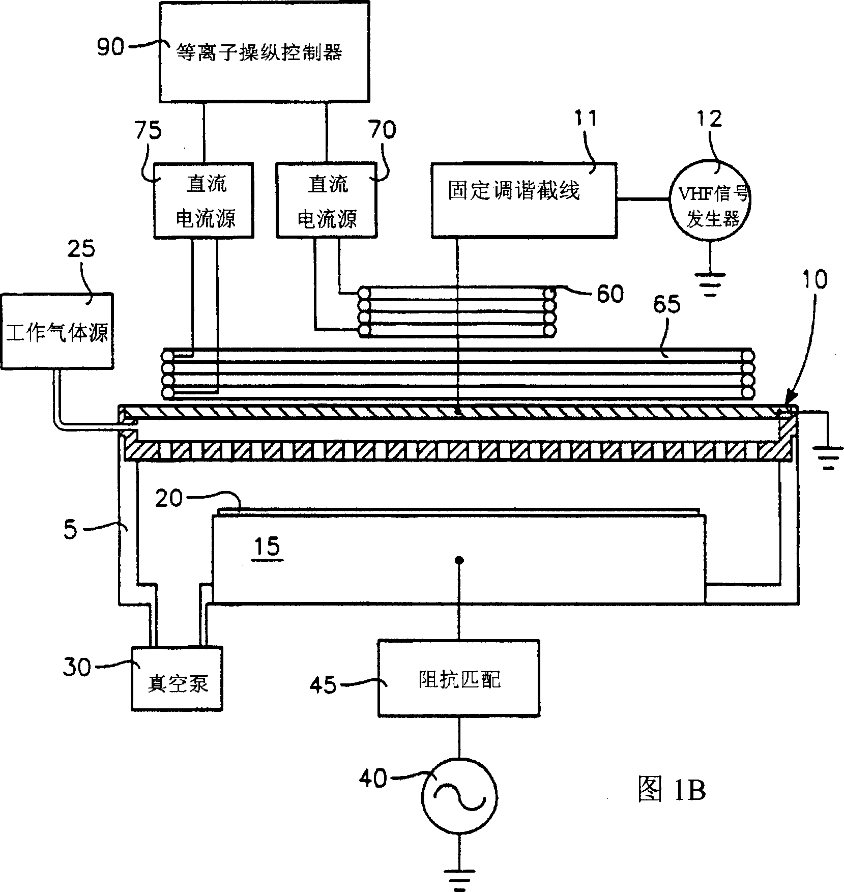
[0046] The plasma ion density distribution exhibited by a given plasma chamber is a function of chamber pressure, gas mixing and diffusion, and source power emission pattern. In the present invention, this distribution is magnetically altered to approximate a predetermined selected or desired distribution to improve process uniformity. The magnetically altered or corrected plasma ion density distribution can improve process uniformity across the wafer or workpiece surface. For this purpose, the magnetically corrected plasma distribution can be non-uniform or also uniform, depending on the needs determined by the user. We have found that by applying pressure to the plasma, the efficiency with which the distribution of the average magnetic field strength is changed to the desired distribution can be effectively improved. Surprising results can be obtained in accordance with this discovery by increasing the radial component of the magnetic field gradient. The radial direction i...


PUM


Abstract

A plasma reactor includes a vacuum enclosure including a side wall and a ceiling defining a vacuum chamber, and a workpiece support within the chamber and facing the ceiling for supporting a planar workpiece, the workpiece support and the ceiling together defining a processing region between the workpiece support and the ceiling. Process gas inlets furnish a process gas into the chamber. A plasma source power electrode is connected to an RF power generator for capacitively coupling plasma source power into the chamber for maintaining a plasma within the chamber. The reactor further includes at least a first overhead solenoidal electromagnet adjacent the ceiling, the overhead solenoidal electromagnet, the ceiling, the sidewall and the workpiece support being located along a common axis of symmetry. A current source is connected to the first solenoidal electromagnet and furnishes a first electric current in the first solenoidal electromagnet whereby to generate within the chamber a magnetic field which is a function of the first electric current, the first electric current having a value such that the magnetic field increases uniformity of plasma ion density radial distribution about the axis of symmetry near a surface of the workpiece support.

Description

[0001] This application claims priority to U.S. Provisional Application Serial No. 60 / 383,194, filed May 22, 2002, by Daniel Hoffman et al., entitled "Magnetic Plasma Control of Capacitively Coupled Plasma reactor." Background technique [0002] Capacitively coupled plasma reactors are used in the preparation of high aspect ratio (High Aspect Ratio) semiconductor microelectronic structures. Such structures typically have narrow, deep channels that pass through one or more thin films formed on a semiconductor substrate (Substrate). Capacitively coupled plasma reactors are used in a variety of processes for making these devices, including dielectric etch processes, metal etch processes, chemical vapor deposition, and others. Such reactors are also used in the preparation of photolithographic masks and in the manufacture of semiconductor flat panel displays. These applications rely on ions in the plasma to intensify or activate the desired process. The density of the plasma on...

Claims


Application Information

Patent Timeline
Patent Type & Authority Applications(China)
IPC IPC(8): H05H1/46H01J27/16H01J37/08H01J37/32H01L21/3065
CPCH01J37/32623H01J37/32091H01J37/3244H01J37/3266H01J37/32
Inventor 丹尼尔·J·后曼马修·L·米勒杨姜久蔡希晔麦可·巴尼斯石川哲也叶洋
Owner APPLIED MATERIALS INC
Learn More