Super gravity liquid absorption dehumidifying and regenerating system

A regenerative system and super-gravity technology, which is applied in air-conditioning systems, heating methods, lighting and heating equipment, etc., can solve the problems of limited improvement range, and achieve the reduction of floor space and space volume, safe and reliable devices, and gas-liquid transmission. The effect of quality improvement

Inactive Publication Date: 2005-10-19
SOUTH CHINA UNIV OF TECH
View PDF3 Cites 12 Cited by
  • Summary
  • Abstract
  • Description
  • Claims
  • Application Information

AI Technical Summary

Problems solved by technology

Although the regeneration efficiency of these systems has impro...

Method used


Image

  • Super gravity liquid absorption dehumidifying and regenerating system
  • Super gravity liquid absorption dehumidifying and regenerating system
  • Super gravity liquid absorption dehumidifying and regenerating system

Examples


Embodiment 1

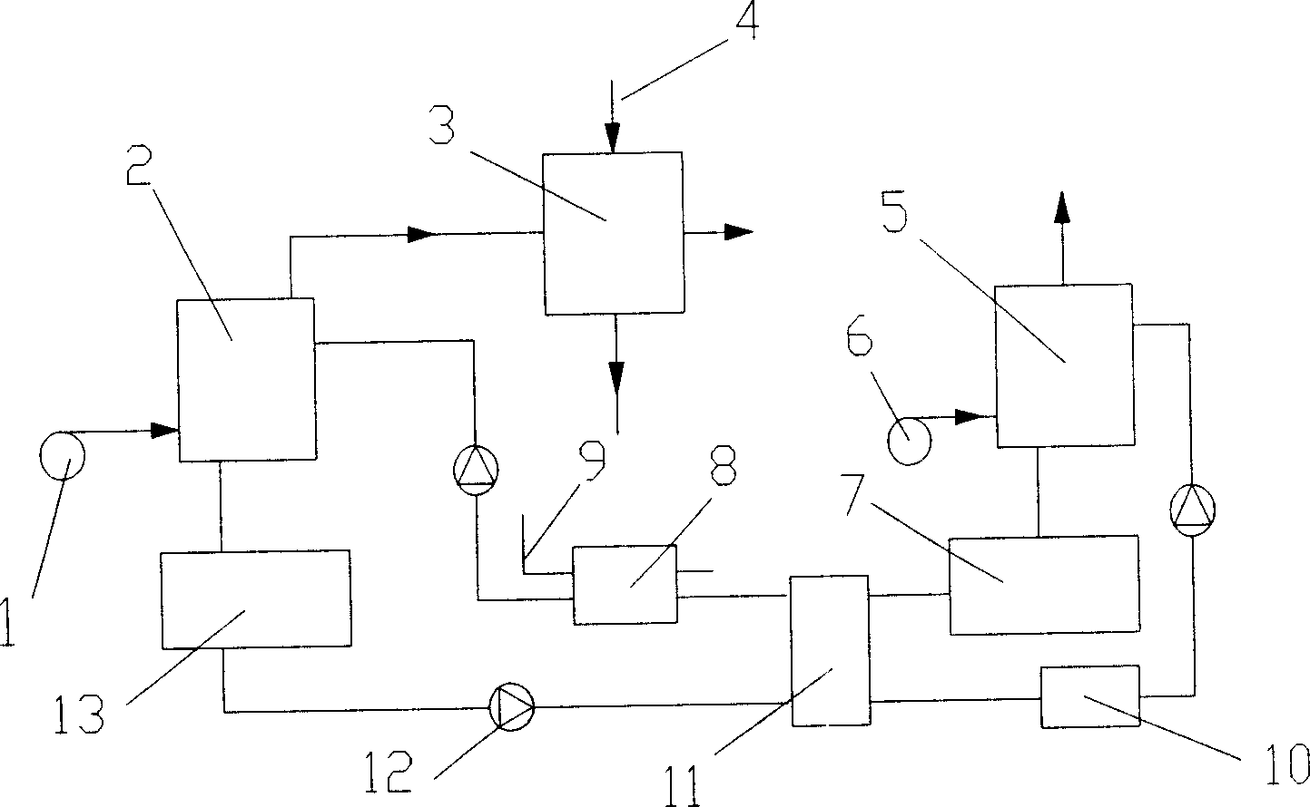
[0034] figure 1 A schematic flow chart of the supergravity liquid absorption dehumidification and regeneration system of the present invention is given, as figure 1 As shown, the supergravity liquid absorption dehumidification and regeneration system includes a supergravity absorber 2 and a supergravity regenerator 5. The supergravity absorber 2 communicates with indoor air, and the supergravity regenerator 5 communicates with outdoor air. The liquid discharge port of the liquid storage tank 13, the tube side of the heat exchanger 11, the regeneration heater 10, the liquid inlet of the supergravity regenerator 5 successively, and the liquid inlet of the supergravity absorber 2 successively connects with the cooler 8, The heat exchanger 11 is connected to the shell side, the hot liquid storage tank 7, and the drain port of the supergravity regenerator 5. The cooler 8 is connected to the cooling water pipe 9. Between the cold liquid storage tank 13 and the heat exchanger 11, the...

Embodiment 2

[0038] Such as figure 1 As shown, the process of the supergravity liquid absorption dehumidification and regeneration system of the present invention is the same as that described in Example 1.

[0039] Figure 4 gives figure 1 Another specific structure of the shown hypergravity absorber 2, such as Figure 4 As shown, the supergravity absorber 2 includes a housing 2-20, a rotating shaft 2-21, a packing bed 2-22, and the housing 2-20 is provided with an air inlet 2-20-1 and an air outlet 2-20-2 , the liquid inlet 2-20-3, the liquid discharge port 2-20-4, the liquid discharge port 2-20-4 is set at the bottom of the shell 2-20, the rotating shaft 2-21 and the air flow through the packing bed 2-22 The direction is vertical, and the air and the liquid LiCl solution are in countercurrent contact in the packed bed 2-22, and the packed bed 2-22 is fixedly connected to the inner end of the rotating shaft 2-21, and a packing metal foam 2-23 and a static liquid distributor are arrang...

Embodiment 3

[0042] Such as figure 1 As shown, the process flow of the supergravity liquid absorption dehumidification and regeneration system of the present invention is the same as that of Embodiment 1.

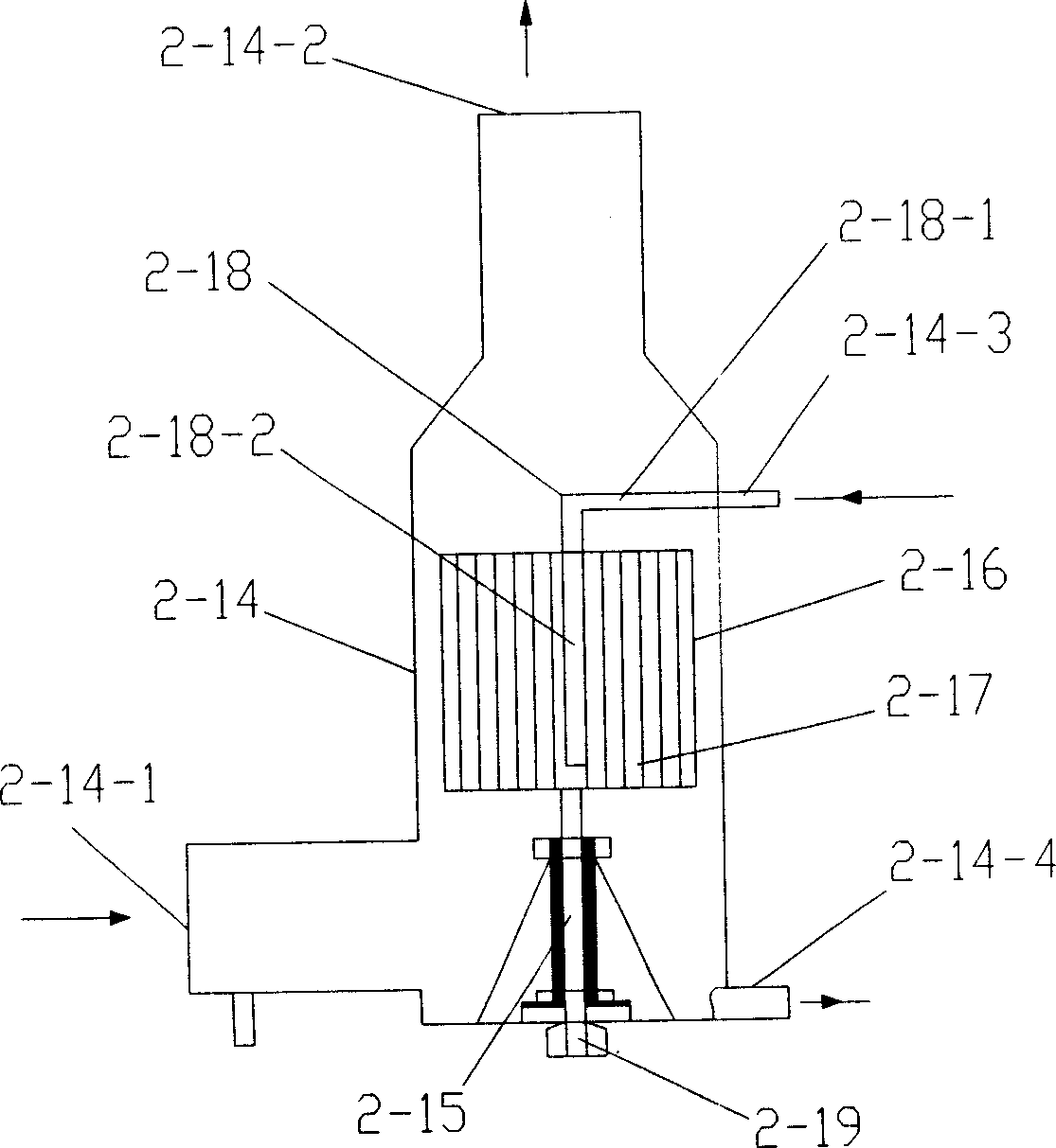
[0043] Such as figure 2 As shown, the structure of the hypergravity absorber 2 is the same as that described in the hypergravity absorber 2 in Example 1, wherein the fillers 2-17 are ceramics, and the liquid is CaCl2 solution.

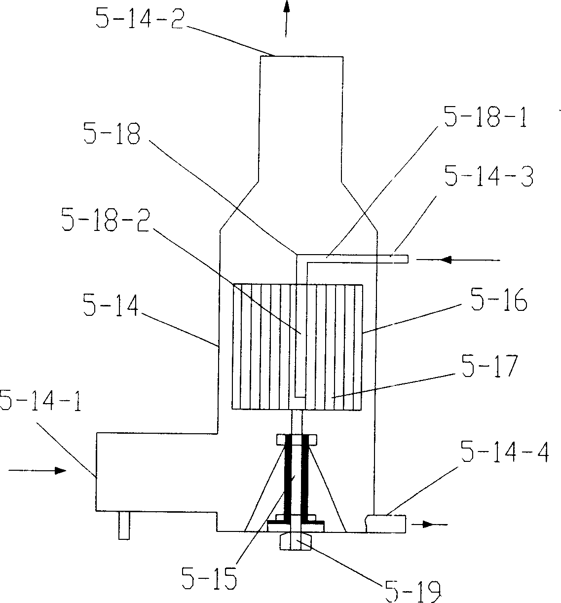
[0044] Such as Figure 5 As shown, the structure of the high-gravity regenerator 5 is the same as the structure of the high-gravity regenerator 6 in Embodiment 2, wherein the filler 5-23 is ceramics, and the liquid is CaCl2 solution.


PUM


Abstract

The supergravity liquid absorbing dehumidifying and regenerating system includes supergravity absorber and supergravity regenerator, the supergravity absorber is communicated with indoor air, and the supergravity regenerator is communicated with outdoor air. Between the supergravity absorber and the supergravity regenerator, there are connected cold liquid storing tank, heat exchanger, regenerating heater, hot storing tank and cooler. The supergravity absorber and the supergravity regenerator are also connected separately to indoor fan and outdoor fan. The supergravity absorber and the supergravity regenerator may be cross flow type or reverse flow type. The present invention has simple structure, low cost, high safety and reliability, high adjustability, high work efficiency, and other advantages.

Description

technical field [0001] The invention relates to liquid absorption dehumidification and regeneration technology, in particular to a supergravity liquid absorption dehumidification and regeneration system. Background technique [0002] The liquid dehumidification system has received extensive attention because of its environmental friendliness, low energy consumption, and the effect of purifying the air while dehumidifying. In traditional liquid dehumidification systems, packed towers and internal cooling dehumidifiers are widely used. Since the packed tower relies on gravity to achieve gas-liquid contact for mass transfer, and the gravity field is weak, the liquid film flows slowly, the gas-liquid contact area is small, the heat and mass transfer process is slow, and a large contact area is required. This kind of equipment is bulky, has low space utilization rate, small air handling capacity, poor dehumidification effect, and is difficult to use i...

Claims


Application Information

Patent Timeline
IPC IPC(8): B01D53/18B01D53/26F24F3/14
Inventor 张立志项辉
Owner SOUTH CHINA UNIV OF TECH
Why Eureka
Try Eureka