Clock synchronizer and clock and data recovery apparatus and method

A synchronizer and clock technology, applied in synchronization devices, data conversion, electrical digital data processing and other directions, can solve problems such as loss of lock

Active Publication Date: 2005-10-19
CIRRUS LOGIC INT SEMICON
View PDF2 Cites 34 Cited by
  • Summary
  • Abstract
  • Description
  • Claims
  • Application Information

AI Technical Summary

Problems solved by technology

The low-bandwidth loop still receives a signal with a large amount of jitter from the high-bandwidth loop, which may occasionally lose lock unless design tradeoffs are made with its performance

Method used


Image

  • Clock synchronizer and clock and data recovery apparatus and method
  • Clock synchronizer and clock and data recovery apparatus and method
  • Clock synchronizer and clock and data recovery apparatus and method

Examples


Embodiment Construction

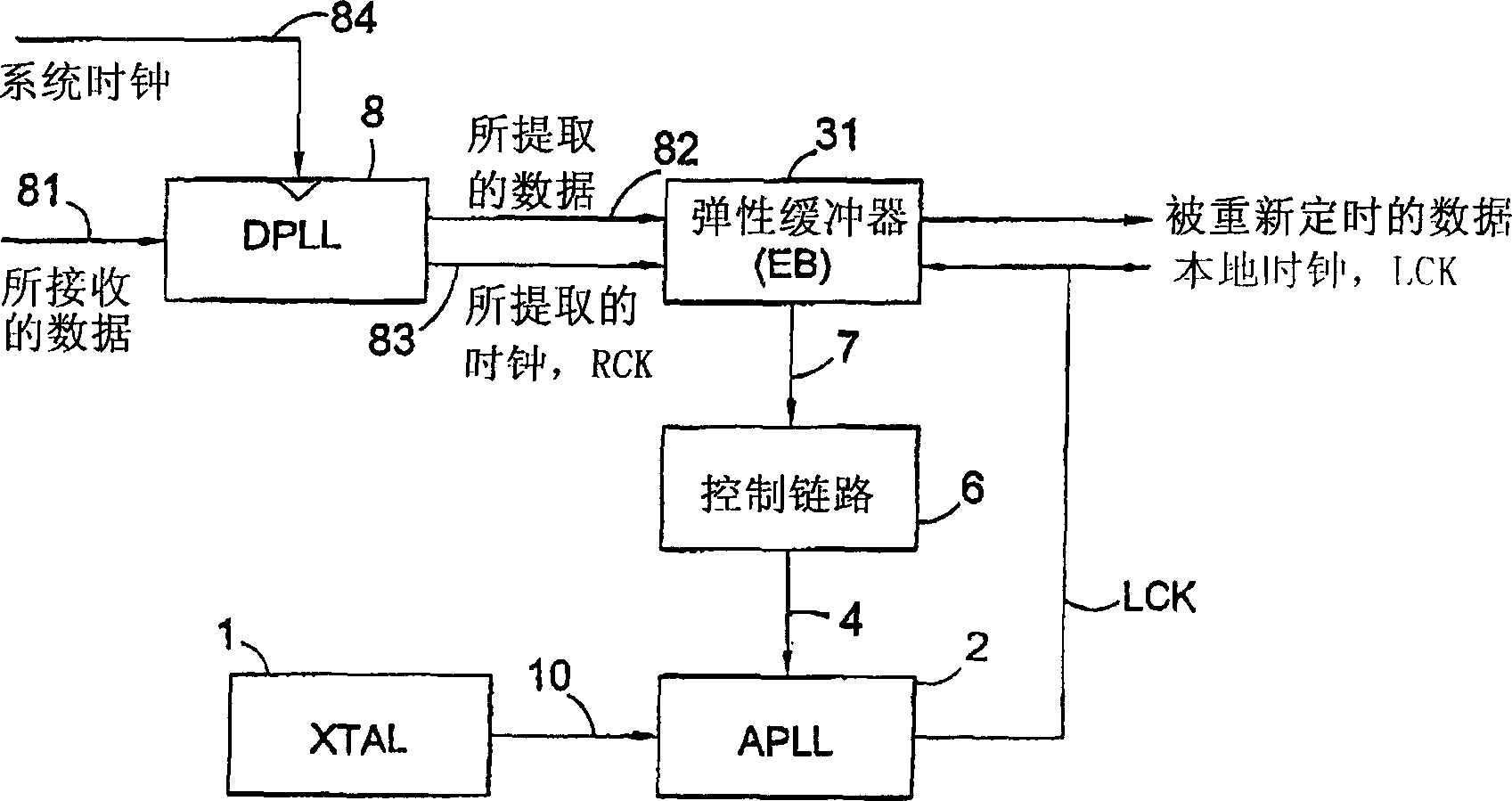
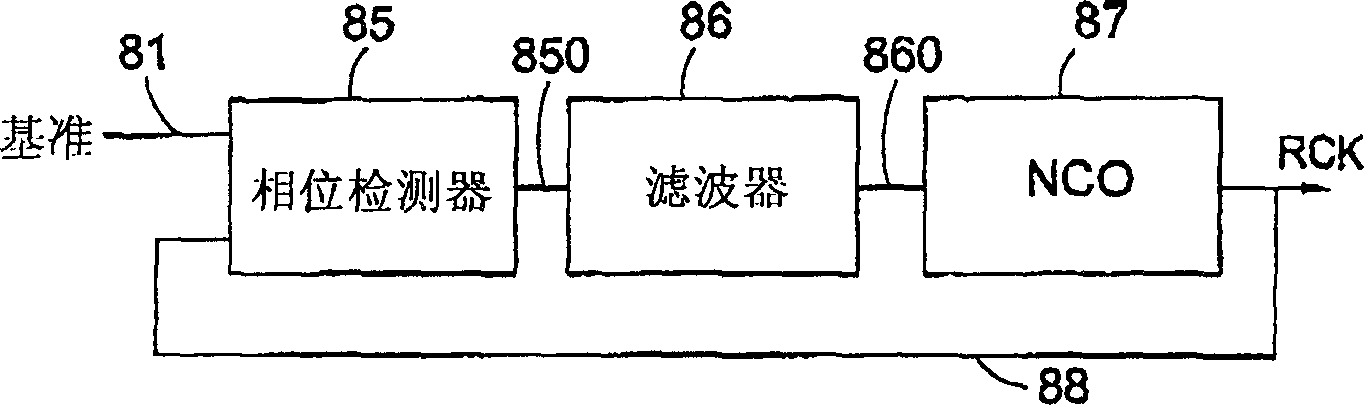
[0124] now refer to figure 2 , The clock and data recovery circuit (system) implementing the present invention includes a clock and data extraction circuit 8, and the clock and data extraction circuit 8 includes a digital phase-locked loop (DPLL). Received data stream 81 containing embedded clock information is supplied to DPLL which is used to lock onto incoming data and generate internal intermediate clock RCK 83 (which should be called received clock) and retimed internal data stream 82 (i.e. the data being extracted). Generation of an internal intermediate clock may also be described as extracting a clock signal from a received data stream, and thus an internal intermediate clock may also be referred to as an extracted clock.

[0125] The extracted data 82 and the extracted clock 83 are provided at the input of the elastic buffer (EB) 31 . EB is used to absorb any short or medium term timing variations between the local and remote clock domains. It also generates a poi...


PUM


Abstract

A clock synchroniser, and clock and data recovery apparatus incorporating the clock synchroniser, are described, together with corresponding clock synchronisation methods. The clock synchroniser incorporates an elastic buffer. A received clock signal RCK is used to clock data into the buffer, and a locally generated clock LCK is used to clock data out of the buffer. The local clock is synthesised using a PLL, and a fill-level signal from the elastic buffer is used to control to local clock frequency to maintain a desired average quantity of data in the buffer, thereby achieving synchronisation of the received and local clocks. In preferred embodiments the fill-level signal is used to control a variable divider in the feedback path of the PLL, which is supplied with a highly stable reference signal. A synchronised, and low-jitter local clock is thus produced. Preferably, the elastic buffer employs counters of relatively wide word width, and a storage array of much reduced depth, read and write pointers being provided by just a few of the least significant bits of the words.

Description

technical field [0001] The present invention relates to a clock synchronizer and to a clock and data recovery device and method. Certain embodiments relate to methods and circuits for recovering a low-jitter clock and data (eg, a jittered data stream) from jittered data. Background technique [0002] figure 1 A data link is shown comprising two systems, each clocked by a respective PLL. The transmitter transmits data at a given rate and the receiver clocks the data using its local clock. However the two clock frequencies may not be exactly the same, either short term or long term. [0003] Short-term variations in frequency will be induced in each clock due to thermal noise or external interference and can be considered as jitter in the corresponding clock. Additional jitter in the data stream can be introduced through intersymbol interference due to the limited bandwidth of the transmit channel or through crosstalk between adjacent cables. [0004] For general purpose ...

Claims


Application Information

Patent Timeline
Patent Type & Authority Applications(China)
IPC IPC(8): G06F5/06G06F5/12H03L7/10H03L7/197H04J3/06H04L7/00H04L7/033H04L25/05
CPCH03L7/197G06F5/06G06F5/12G06F2205/061H03L7/10H04J3/0632H03L7/1075H04L7/00
Inventor 保罗·莱索
Owner CIRRUS LOGIC INT SEMICON
Why Eureka
Try Eureka