Permanent magnet offset radial magnetic bearing

A technology of permanent magnet bias and magnetic bearing, applied in the directions of bearings, shafts and bearings, mechanical equipment, etc., can solve the problems of complex structure of the same polarity, low suspension power consumption, and many control coils, etc., and shorten the axial direction. The effect of occupying space, reducing size and weight, and broad application prospects

Inactive Publication Date: 2005-11-09
NANJING UNIV OF AERONAUTICS & ASTRONAUTICS
View PDF0 Cites 28 Cited by
  • Summary
  • Abstract
  • Description
  • Claims
  • Application Information

AI Technical Summary

Problems solved by technology

It has high rigidity and can be precisely controlled, but its volume, weight and power consumption are relatively large
The second type is passive magnetic bearings. The levitation force of this magnetic bearing is completely provided by permanent magnets. The required controller is simple, and the levitation power consumption is small, but the stiffness and damping are small, and it is generally used in only one direction. Supporting objects or reducing the load acting on traditional bearings, high-temperature superconducting magnetic bearings belonging to passive magnetic bearings can obtain stable suspension by using permanent magnets due to the diamagnetism of superconductors, but due to the limitations of the research status of high-temperature superconducting materials , currently of little value
[0003] At present, the structure forms of permanent magnet bias radial magnetic bearings researched internationally are divided into heteropolar and homopolar structures. The axial length of heteropolar structures can be made shorter, but hysteresis loss will occur, while homopolar structures The hysteresis loss of the magnetic bearing with the structure is greatly reduced, but the structure of the ordinary homopolar structure is complicated, the required control wire package is large, and the axial space occupied is large, which is not conducive to the improvement of the critical speed of the rotor.

Method used


Image

  • Permanent magnet offset radial magnetic bearing
  • Permanent magnet offset radial magnetic bearing

Examples


Embodiment Construction

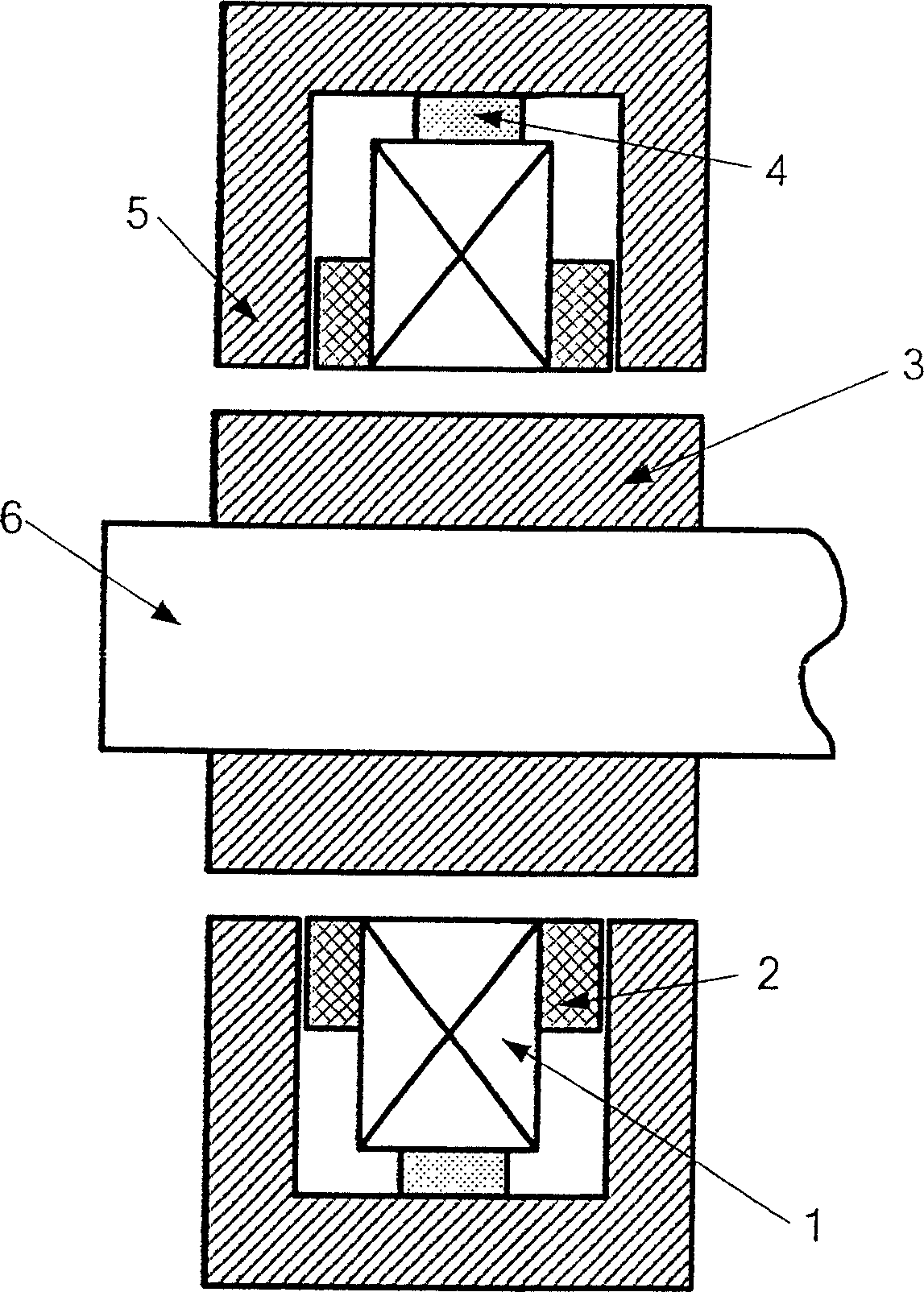
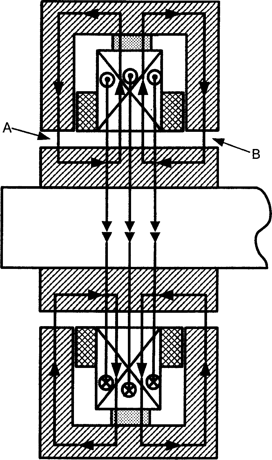
[0011] figure 1 It is a schematic diagram of the permanent magnet bias radial magnetic bearing structure of the present invention. The radial stator 1 in the figure is made of laminated silicon steel sheets and has a two-pole structure. Control windings 2 are wound on four teeth, and the two opposite The windings on each tooth are connected in series, the annular permanent magnet 4 is mounted on the middle position outside the radial stator 1, the outer magnetic pole core 5 and the rotor iron core 3 are made of electric pure iron, and the outer magnetic pole core 5 is set in the radial direction On the outer circle of the stator 1 , its inner end surface is in contact with the annular permanent magnet 4 , and the rotor core 3 sleeved on the rotor 6 is placed in the stator 1 . The bias magnetic flux generated by the annular permanent magnet passes through the outer magnetic pole core, air gap A (or air gap B), rotor core, radial air gap and radial stator in turn to form a loop,...


PUM


Abstract

The invention relates to a permanent-magnet offset radial magnetic bearing. It includes radial stator, control coil, circle permanent magnet, exterior magnetic pole iron core and rotator covered by rotator iron core. The permanent-magnet offset radial magnetic bearing has advantage of simple structure, small volume, and light weight. It has a broad application prospect in kinds of magnetic suspension systems that take up small space on radial direction.

Description

1. Technical field [0001] The permanent magnetic bias radial magnetic bearing of the invention belongs to the hybrid magnetic bearing in the magnetic bearing. 2. Background technology [0002] At present, magnetic bearings are divided into the following types according to the way the magnetic force is provided: The first type is active magnetic bearings. There is a bias current in the magnetic bearing coil to provide a bias magnetic field, and the control current generated by the control current flows through the control winding. The magnetic flux is superimposed with the bias flux to create a controllable levitation force. It has high rigidity and can be precisely controlled, but its volume, weight and power consumption are relatively large. The second type is passive magnetic bearings. The levitation force of this magnetic bearing is completely provided by permanent magnets. The required controller is simple, and the levitation power consumption is small, but the stiffnes...

Claims


Application Information

Patent Timeline
Patent Type & Authority Applications(China)
IPC IPC(8): F16C32/04
Inventor 梅磊邓智泉王晓琳赵旭升
Owner NANJING UNIV OF AERONAUTICS & ASTRONAUTICS
Why Eureka
Try Eureka