Transistor measuring instrument

A measuring instrument and transistor technology, which is applied in the direction of measuring electricity, measuring devices, measuring electrical variables, etc., and can solve the problems of large volume, high cost, and complex structure.

Inactive Publication Date: 2005-11-09
HEILONGJIANG UNIV
View PDF0 Cites 10 Cited by
  • Summary
  • Abstract
  • Description
  • Claims
  • Application Information

AI Technical Summary

Problems solved by technology

[0003] The purpose of the present invention is to provide a transistor measuring instrument to overcome the defects of complex structure, large volume and high cost of existing transistor measuring instruments

Method used


Image

  • Transistor measuring instrument
  • Transistor measuring instrument
  • Transistor measuring instrument

Examples


specific Embodiment approach 1

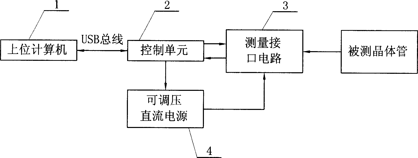
[0005] Specific implementation mode one: the following combination figure 1 This embodiment will be specifically described. This embodiment is composed of a host computer 1, a control unit 2, a measurement interface circuit 3, and an adjustable DC power supply 4. The communication port of the host computer 1 is connected to the communication port of the control unit 2 through a USB bus, and an output of the control unit 2 connected to the controlled end of the adjustable voltage DC power supply 4, the other output end of the control unit 2 is connected to an input end of the measurement interface circuit 3, the output end of the measurement interface circuit 3 is connected to the input end of the control unit 2, and the adjustable voltage DC The output terminal of the power supply 4 is connected to the power supply terminal of the measurement interface circuit 3 .

specific Embodiment approach 2

[0006] Specific implementation mode two: the following combination figure 2 This embodiment will be specifically described. The difference between this embodiment and Embodiment 1 is: the control unit 2 selects the single-chip microcomputer chip U1, the model of the single-chip microcomputer chip U1 is PIC16C765, the pin 23 and pin 24 of the single-chip microcomputer chip U1 are connected to the host computer 1 through the USB bus, and the measurement interface circuit 3 is composed of The twenty-third resistor R23, the twenty-fourth resistor R24, the twenty-fifth resistor R25, the first relay J1, the second relay J2, the third relay J3, the second diode N2, the third diode N3, The fourth diode N4 and slot J6 are formed, one end of the twenty-third resistor R23 is connected to the pin 19 of the single-chip microcomputer chip U1, and the other end of the twenty-third resistor R23 is connected to the pin 2 of the single-chip microcomputer chip U1 and the pin 1 of the No. 1 rela...

specific Embodiment approach 3

[0008] Specific implementation mode three: the following combination figure 2 This embodiment will be specifically described. The difference between this embodiment and the second embodiment is that it also includes a warning circuit 6, the warning circuit 6 is composed of a third resistor R3, a field effect transistor M11 and a light emitting diode N1, and one end of the third resistor R3 is connected to the fifth resistor R5. One end, the other end of the third resistor R3 is connected to the drain of the field effect transistor M11, the source of the field effect transistor M11 is grounded, the gate of the field effect transistor M11 is connected to the cathode of the light-emitting diode N1, and the anode of the light-emitting diode N1 is connected to the single-chip microcomputer chip U1 29 feet. Other components and connections are the same as those in Embodiment 2. When testing parameters such as the amplification factor, reverse breakdown voltage, and reverse leakag...


PUM


Abstract

A transistor measuring device is an instrument that identifies polarity of each pin of transistor and various parameters. It is composed of a carry computer, a control unit, a measure interface circuit and a direct current power supply with adjustable press. computer and control unit communication interfaces are linked together; One of control unit exportation interfaces is linked with power supply control interface; The other interface of control unit is linked with inputend of interface circuit input; control unit exportation interface is linked with control unit input interface, and power supply output interface is linked with the power supply. control unit provides different voltages to the transistor pins through control unit and people can judge these pins attributes according to whether the PN stanza can transmit electric current. power supply works when people are measuring parameters. computer adopts a normal personal computer and control unit chooses a low cost, small volume chip. Moreover,the situation that computer is linked with control unit through a main line of USB makes the invention more popular.

Description

Technical field: [0001] The invention relates to an instrument for identifying the polarity of each pin of a transistor and measuring various parameters of the transistor. Background technique: [0002] Traditional measuring instruments for various parameters of transistors are generally realized by complex hardware circuits, resulting in high price of finished products, single function, bulky volume, and limited range of use and accuracy. Although there are also intelligent transistor measuring instruments, most of these instruments use special-purpose computers as the core and are equipped with corresponding special-purpose software and hardware boards. Due to the large hardware base of this kind of scheme, they are still bulky and expensive. Invention content: [0003] The purpose of the present invention is to provide a transistor measuring instrument to overcome the defects of complex structure, large volume and high cost of existing transistor measuring instruments. ...

Claims


Application Information

Patent Timeline
IPC IPC(8): G01R31/26
Inventor 石广范闫广明李季刚王冠然成责果
Owner HEILONGJIANG UNIV
Why Eureka
Try Eureka