Plasma fluidized bed for treating material under normal temperature atmosphere and method thereof

A plasma and atmospheric pressure technology, applied in chemical instruments and methods, chemical/physical processes, etc., can solve problems such as affecting the use efficiency of plasma fluidized beds, limiting the types of modified materials, affecting the scope of application, etc. Low cost, wide range of effects

Inactive Publication Date: 2005-12-21
INST OF PHYSICS - CHINESE ACAD OF SCI
View PDF0 Cites 18 Cited by
  • Summary
  • Abstract
  • Description
  • Claims
  • Application Information

AI Technical Summary

Problems solved by technology

The device can only generate plasma under certain vacuum conditions, vacuum equipment will increase operating costs, and the existence of vacuum conditions affects its scope of application
[0003] There is also a direct current plasma fluidized bed, such as the intermittent fluidized bed introduced in Document 2: A direct current, plasmafluidized bed reactor: its characteristics and application in diamondsynthesis, POWDER TECHNOLOGY, 88 (1996) 65-70, the intermittent Fluidized bed such as figure 2 As shown, the argon gas at the bottom fluidizes the powder particles, and the reaction gas enters from the side of the wall. The plasma is generated by drawing an arc between the cathode and anode. In the fluidized bed, the reaction gas enters from the side of the gas distributor. Due to the high temperature of the electrode, it needs to be cooled with cooling water, which also limits the types of modified materials.
Due to the existence of these shortcomings, the use efficiency of these two types of plasma fluidized beds has been affected.

Method used


Image

  • Plasma fluidized bed for treating material under normal temperature atmosphere and method thereof
  • Plasma fluidized bed for treating material under normal temperature atmosphere and method thereof
  • Plasma fluidized bed for treating material under normal temperature atmosphere and method thereof

Examples


specific Embodiment approach

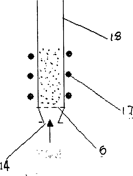
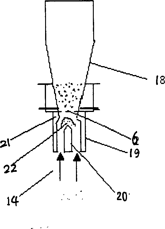
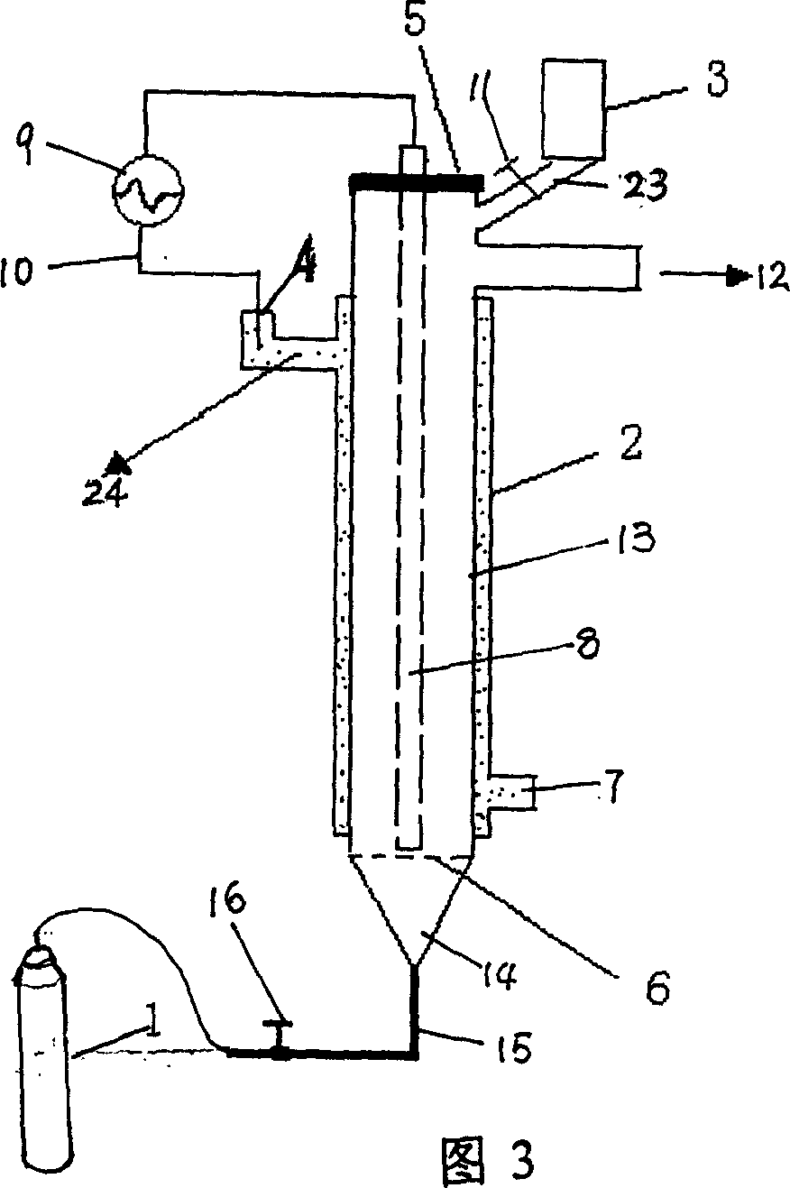
[0062] 1. For example, use Figure 3 to realize the modification of the hydrophilic properties of calcium carbonate powder materials: calcium carbonate powder is a material with very good hydrophilic properties. To make it into a non-hydrophilic material, it only needs to be coated on the surface of the powder A layer of low surface energy material is sufficient.

[0063] 1. First pass ordinary tap water into the hollow shell of the outer electrode of the plasma fluidized bed, and insert one pole of the high-voltage AC power supply into the conductive liquid for fixed connection; or directly connect the metal outer electrode to one pole of the high-voltage AC power supply connect;

[0064] 2. Put the gas distributor with a pore size of 5 microns into the bottom of the fluidized bed and install it;

[0065] 3. add the calcium carbonate powder that diameter is about 5 microns in funnel 3 again, then open valve and this powder material is delivered the calcium carbonate powder of...


PUM


Abstract

The invention relates to a kind of plasma sulfurization bed processing materials at room temperature atmospheric pressure. It includes: the bed body produced by insulating material, the downer port of which equips a gas divider, and under the gas divider equips an infundibular gas inlet, which is connected to the gas source to the conduit with gas flowmeter; the side surface of the upper bed body has gas exit, leave a hole above the position of the gas exit of the bed body; the hole equips a conduit with valve, which is linked through a feed-in tundish; set a outer electrode below the gas exit of the bed body to a segment of the outer surface of the gas divider, and the outer electrode is connected to one end of the high voltage alternating current supply; the inner electrode is inserted into the bed body, sealed and fixed at the upper port of the bed body through a insulating board; the inner electrode reaching outside the upper port of the bed body is connected to the other end of the high voltage alternating current supply. The processing method of the invention can operate at room temperature atmospheric pressure without needing vacuum equipment, so its operating cost is low. It won't damage the powdered material, and is suitable to wide area of modified materials.

Description

technical field [0001] The invention relates to a plasma treatment device for modifying materials, in particular to a plasma fluidized bed and a treatment method for treating materials at normal temperature and atmospheric pressure. technical background [0002] At present, fluidized bed equipment and technology are relatively mature, and have been widely used in chemical enterprises. The technology of treating materials with plasma is relatively mature, and the applicant has applied for several patents on this subject. The plasma fluidized bed made by combining physical and chemical methods has just begun to be developed in the world. According to foreign reports, there is a radio frequency plasma fluidized bed, such as document 1: Plasma fluidized bedimaging and possible strong coupling effects, APPLIED PHYSICSLETTERS, Vol76No.18, 2000.5. Introduced: This plasma fluidized bed mainly consists of four parts: fluidization gas control, gas distributor, radio frequency inducti...

Claims


Application Information

Patent Timeline
Patent Type & Authority Applications(China)
IPC IPC(8): B01J8/24
Inventor 陈光良杨思泽张谷令王久丽刘元富冯文然刘赤子
Owner INST OF PHYSICS - CHINESE ACAD OF SCI
Why Eureka
Try Eureka