Electrophotographic photoreceptor and image forming apparatus provided with the same

A photoreceptor and electrophotography technology, applied in optics, electrical recording, instruments, etc., can solve the problems of unrealized electrical characteristics and stability of photoreceptors, reduced responsiveness, and reduced charged potential, etc., to achieve characteristic stability Excellent, excellent resistance to oxidizing gas, long-term stable formation effect

Inactive Publication Date: 2005-12-28
SHARP KK
View PDF3 Cites 2 Cited by
  • Summary
  • Abstract
  • Description
  • Claims
  • Application Information

AI Technical Summary

Problems solved by technology

[0020] In addition, when the antioxidants disclosed in JP-A-62-105151, JP-8-292587, and JP-10-282696 are added to the photosensitive layer, there are also changes in the photosensitive wavelength and the like. Decreased sensitivity and responsiveness, etc. During the electrophotography process such as repeated charging, exposure, and static elimination, problems such as a decrease in charge potential and an increase in residual potential occur
[0021] As described above, in the prior art, there has been no photoreceptor that satisfies both good electrical characteristics and its stability.

Method used

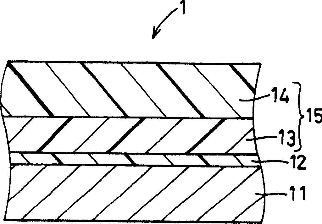
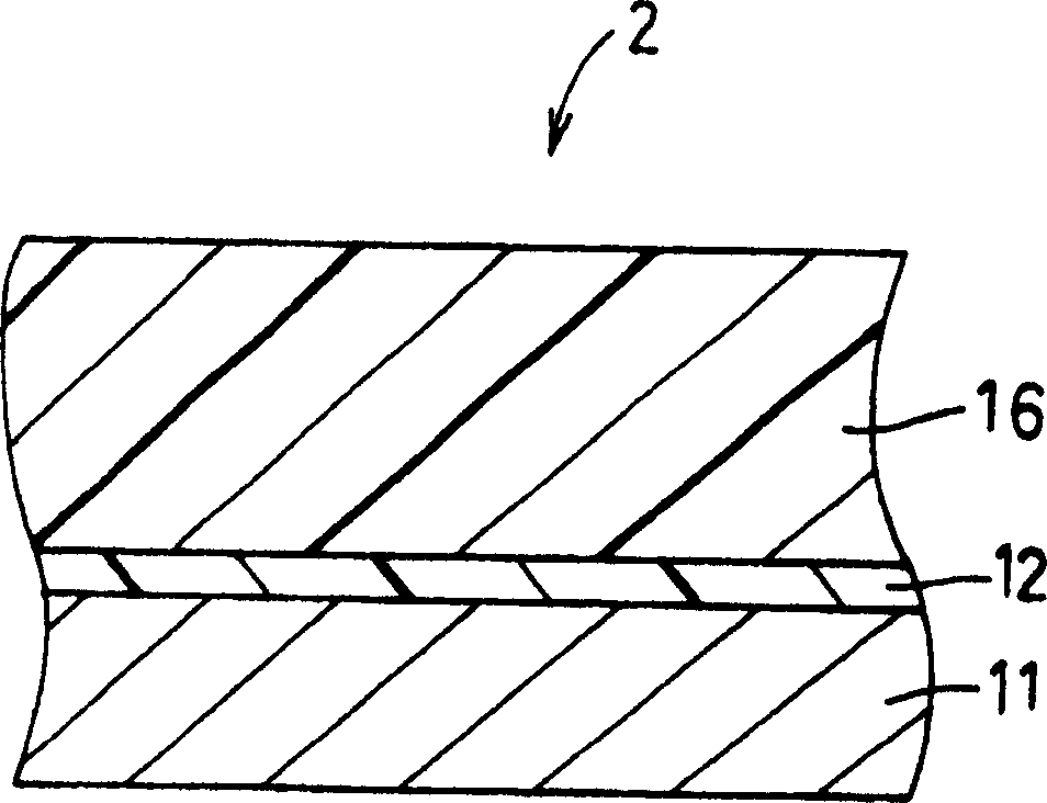
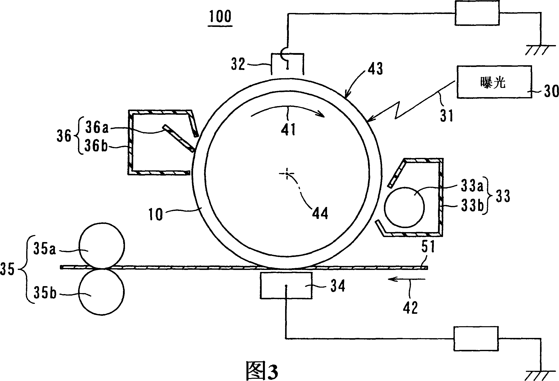

Image

  • Electrophotographic photoreceptor and image forming apparatus provided with the same
  • Electrophotographic photoreceptor and image forming apparatus provided with the same
  • Electrophotographic photoreceptor and image forming apparatus provided with the same

Examples


Embodiment

[0142] The present invention will be described in more detail below using examples and comparative examples, but the present invention is not limited to the content described below.

manufacture example

[0144] In the following examples and comparative examples, an enamine compound represented by the following structural formula (3a) was used as the charge-transporting substance.

[0145]

[0146] The method for producing the enamine compound represented by the above structural formula (3a) will be described below. [Production of Enamine Compound Represented by Structural Formula (3a)] (Production Example 1-1) Production of Enamine Intermediate

[0147] Add 4.9 g (1.0 molar equivalent) of N-(p-methoxyphenyl)-α-naphthylamine represented by the following structural formula (4) and diphenylacetaldehyde represented by the following structural formula (5) to 100 mL of toluene 4.1 g (1.05 molar equivalent) and 46 mg (0.01 molar equivalent) of DL-10-camphorsulfonic acid were heated and reacted for 6 hours while the by-product water and toluene were azeotropically discharged out of the system. After the reaction was completed, the reaction solution was concentrated to about one-te...

manufacture example 1-2

[0152] (Production example 1-2) Production of enamine-aldehyde intermediate

[0153] In 100 mL of N,N-dimethylformamide (DMF), slowly add 3.4 g (1.2 molar equivalents) of phosphorus oxychloride under ice-cooling conditions, and stir for about 30 minutes to prepare the Wilsmeyer reagent . To this solution, 7.9 g (1.0 molar equivalent) of the enamine intermediate represented by the above structural formula (6) obtained in Production Example 1-1 was gradually added under ice-cooling. Then, it was heated slowly, the reaction temperature was raised to 80°C, and it was stirred for 3 hours while maintaining heating at 80°C. After the reaction, the reaction solution was left to cool, and slowly added to 800 mL of cold 4N aqueous sodium hydroxide solution to cause precipitation. The generated precipitate was filtered, washed sufficiently with water, and then recrystallized from a mixed solvent of ethanol and ethyl acetate to obtain 7.2 g of a yellow powdery compound.

[0154] The ob...


PUM


Abstract

The present invention provides an electrophotographic photoreceptor, which has excellent electrical properties such as chargeability, sensitivity, and responsiveness, and has excellent resistance to oxidizing gases, and has excellent stable properties without degrading the above-mentioned good electrical properties even after repeated use. sex. An undercoat layer is provided between the electroconductive support and the photosensitive layer of the electrophotographic photoreceptor, and the undercoat layer contains the amine compound represented by the above general formula (1).

Description

technical field [0001] The present invention relates to an electrophotographic photoreceptor for forming images by electrophotography and an image forming apparatus having the photoreceptor. Background technique [0002] An electrophotographic image forming apparatus that forms an image using electrophotography is often used as a copying machine, a printing machine, a facsimile machine, or the like. In an electrophotographic image forming apparatus, an image is formed by electrophotography using a photoconductive electrophotographic photoreceptor (hereinafter also simply referred to as a photoreceptor). Electrophotography is one of information recording means utilizing the photoconductive phenomenon of a photoreceptor, and is performed as follows. [0003] First, the photoreceptor is placed in a dark place, the surface of the photoreceptor is uniformly charged by a charging device (charging means), and then exposed according to image information to selectively discharge the...

Claims


Application Information

Patent Timeline
Patent Type & Authority Applications(China)
IPC IPC(8): G03G5/06G03G5/14
CPCG03G5/142
Inventor 内野彰子福岛功太郎有村拓也
Owner SHARP KK
Why Eureka
Try Eureka