End effector assembly for supporting substrates

An end effector and support technology, which is used in semiconductor/solid-state device manufacturing, electrical components, conveyor objects, etc., and can solve problems such as fracture, particle substrate damage, and pollution treatment.

Inactive Publication Date: 2006-01-25
APPLIED MATERIALS INC
View PDF4 Cites 18 Cited by
  • Summary
  • Abstract
  • Description
  • Claims
  • Application Information

AI Technical Summary

Problems solved by technology

Rubber pads that melt away and stick to the back of the substrate are undesirable as it becomes a potential contamination and a problem for subsequent disposal
In addition, when the rubber pad is removed from the end effector, it can happen that the end effector scratches the backside of the substrate, which can lead to particle generation and damage or breakage of the substrate
In addition, if the rubber pad melts away, it is difficult to replace the rubber pad

Method used


Image

  • End effector assembly for supporting substrates
  • End effector assembly for supporting substrates
  • End effector assembly for supporting substrates

Examples


Embodiment Construction

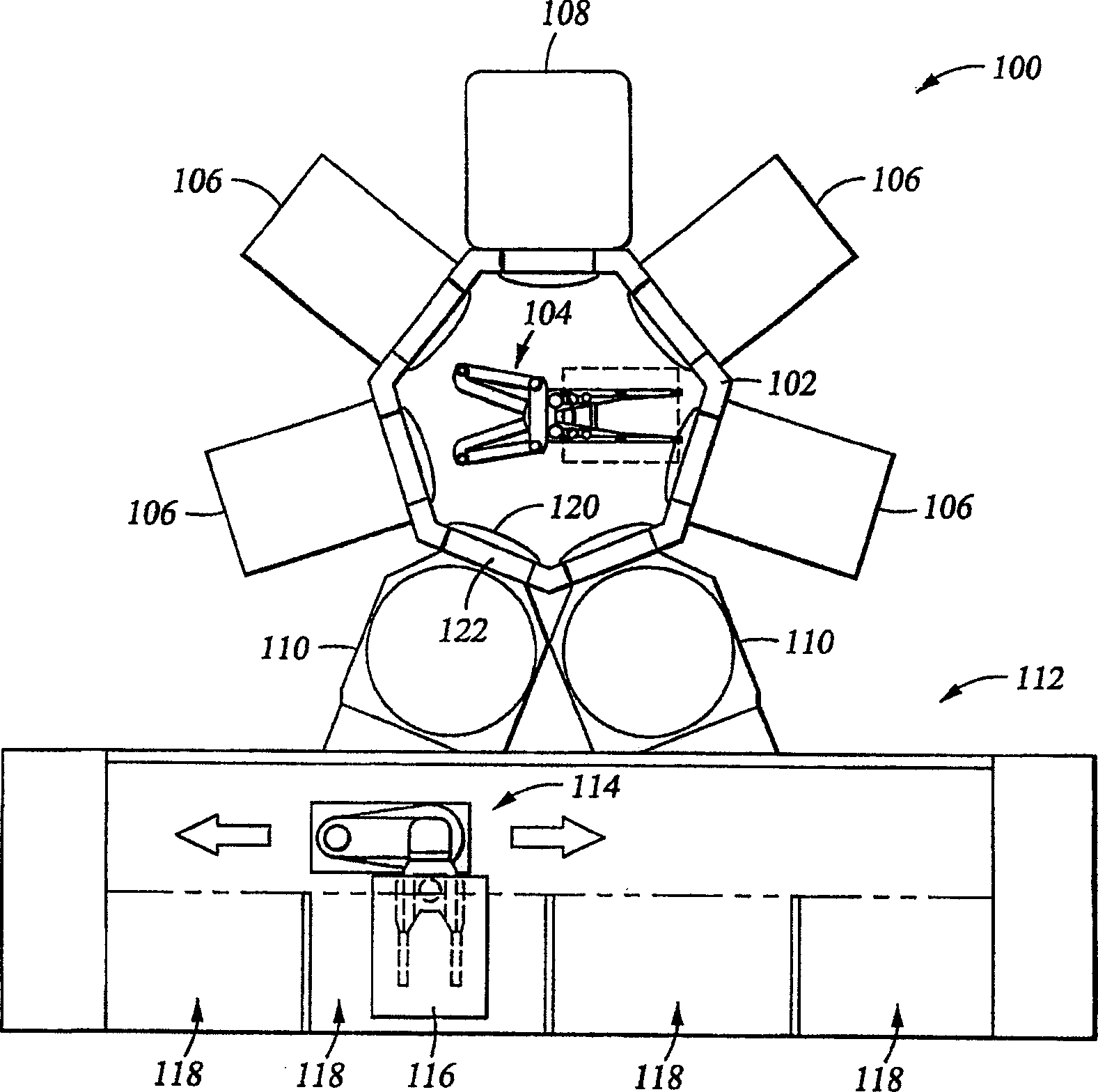
[0074] figure 1 A schematic layout of cluster tool 100 is shown. The cluster tool 100 generally includes a delivery chamber 102 having a first delivery robot 104 disposed therein. The transport chamber 102 is surrounded by a plurality of processing chambers 106 , a thermal processing chamber 108 and at least one load lock chamber 110 . The load lock chamber 110 is coupled between the transfer chamber 102 and a factory interface 112, and two of the load lock chambers 110 are indicated at figure 1 middle. One clustering tool that may be employed to benefit from the present invention is manufactured by AKT Corporation, a company owned by Applied Materials, Inc. of Santa Clara, California, USA.

[0075] The fab interface 112 generally includes a second transfer robot 114 that transfers substrates 116 between the load lock chambers 110 and a plurality of wafer storage cassettes 118 coupled to or disposed within the fab interface 112 . The second delivery robot 114 can be made ...


PUM


Abstract

Generally, an end effector assembly for a substrate transfer robot is provided. In one embodiment, an end effector assembly for supporting a quadrilateral substrate during substrate transfer includes an end effector having an inner edge support disposed on a first end and a first outer edge support disposed on a distal end. The first end of the end effector is adapted for coupling to a robot linkage. The first inner edge support has a face that is oriented parallel to and facing the face of the first outer edge support. This configuration of edge supports captures the substrate to the end effector thereby minimizing substrate slippage during transfer. In another embodiment, lateral guides may be utilized to further enhance capturing the substrate along the edges of the substrate open between the inner and outer edge supports.

Description

technical field [0001] Embodiments of the present invention relate to an end effector assembly for supporting a substrate. Background technique [0002] Thin film transistors (TFTs) are traditionally fabricated on large glass substrates or panels for use in monitors, flat panel displays, solar cells, personal digital assistants (PDAs), mobile phones, and similar products. TFTs are fabricated in a cluster tool by sequential deposition of different layers in a vacuum chamber, including amorphous silicon, doped and undoped silicon oxide, silicon nitride and the like, In this case, the vacuum chamber is arranged around a central conveying chamber. Fabrication of good quality polysilicon precursors used in these structures must control the hydrogen content of the film to less than 1%. In order to achieve this low hydrogen content, the post-deposition heat treatment of the film must be performed at a temperature of about 550°C. [0003] Therefore, the robotic arms used to move ...

Claims


Application Information

Patent Timeline
Patent Type & Authority Applications(China)
IPC IPC(8): H01L21/68H01L21/687
CPCH01L21/68707Y10S414/141Y10S294/902B65G49/062H01L21/67742H01L21/68721H01L21/68735
Inventor 温德尔·T·布伦尼格松本贵之威廉·N·斯特林比利·C·梁
Owner APPLIED MATERIALS INC
Why Eureka
Try Eureka