

Secondary battery negative pole (anode) and making method
A secondary battery and negative electrode technology, applied in secondary batteries, electrode manufacturing, battery electrodes, etc., can solve problems such as poor conductivity and electrode failure, and achieve the effects of increasing specific energy, improving life, and uniform volume expansion
- Summary
- Abstract
- Description
- Claims
- Application Information
AI Technical Summary
Problems solved by technology
Method used
Image

Examples
Embodiment 1
[0023] Embodiment 1: Preparation and charge and discharge performance of amorphous silicon negative electrode (anode) electrode
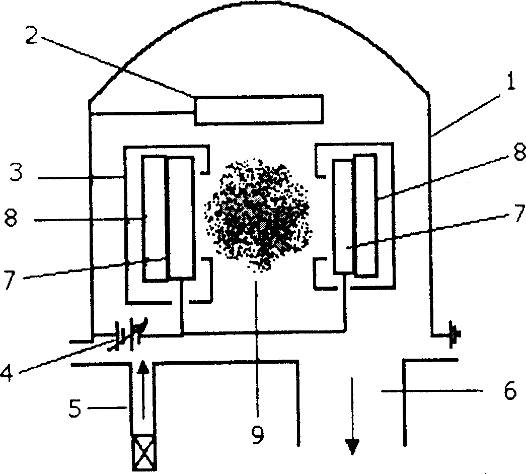
[0024] Place two commercially available silicon targets in parallel in a magnetron sputtering apparatus as figure 1 As shown, the silicon target is placed oppositely as the cathode, the stainless steel bell jar is grounded as the anode, and the external magnetic field is perpendicular to the target surface. Place a piece of copper foil, nickel foil, copper-plated or / and nickel-plated iron foil on the sample holder between two silicon targets as the electrode collector, and then evacuate to 10 -4 Below Pa. Introduce high-purity argon to make the argon pressure reach 0.2Pa. Then, apply a voltage of 300V to the silicon target, control the current to 0.1A, take out the current collector after sputtering for 2 hours, and obtain the negative (anode) electrode of the present invention, and its thickness is 5 μm after measurement. Since copper foil and c...
Embodiment 2
[0026] Embodiment 2: Preparation and charge and discharge performance of amorphous Si-Sn negative pole (anode) electrode
[0027] The preparation method of the binary alloy is the same as that of Example 1. Place two commercially available silicon targets and two metal M targets in parallel in the magnetron sputtering apparatus, and place a piece of copper foil, nickel foil, copper-plated or / and nickel-plated iron on the sample holder among the four targets foil as the electrode current collector, and then evacuated to 10 -4 Below Pa. Introduce high-purity argon to make the argon pressure reach 0.1Pa. Then, apply a voltage to 200V to the silicon target, control the current to 0.15A, apply a voltage to the metal Sn target to 200V, and use a current of 0.2A, take out the current collector after sputtering for 3 hours, and obtain the negative electrode (anode) of the present invention electrode. According to elemental analysis, its composition is Si 0.7 sn 0.3 , with a thic...
Embodiment 3
[0030] Embodiment 3: preparation and charging and discharging performance of amorphous Si-Sb negative electrode (anode) electrode
[0031] The preparation method of this alloy is the same as that of Example 2. Vacuum to 10 -4 Below Pa, pass high-purity argon to make the argon pressure reach 0.5Pa. Then, apply a voltage to 100V to the silicon target, control the current to 0.15A, apply a voltage to the metal Sb target to 200V, and a current of 0.3A, take out the current collector after sputtering for 2 hours, and obtain the negative electrode (anode) of the present invention electrode. According to elemental analysis, its composition is Si 0.6 Sb 0.4 , with a thickness of 15 μm.
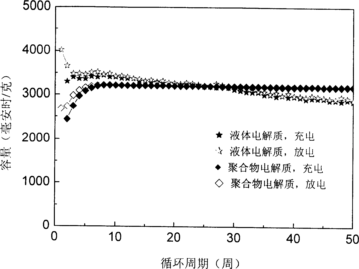
[0032] Its cycle life curve and Figure 4 resemblance. Si 0.6 Sb 0.4 The electrodes showed good cycling performance in both electrolytes. In 1MLiPF 6 (EC:DEC=1:1V / V%) In the electrolyte, the first cycle has the highest capacity, up to 2517mAh / g, and the irreversible capacity is 2% of the in...
PUM
| Property | Measurement | Unit |
|---|---|---|
| thickness | aaaaa | aaaaa |
| thickness | aaaaa | aaaaa |
| thickness | aaaaa | aaaaa |
Abstract
Description
Claims
Application Information