Method and device for welding thermoplastic material shaped parts, particularly for contour-welding three-dimensional shaped parts

A technology for thermoplastics and molded parts, which is applied in the field of welded and molded thermoplastic molded parts, especially contour welded three-dimensional molded parts and devices, which can solve problems such as industrial application obstacles and process window narrowing, and achieve tolerance compensation, The effect of expanding the process window and reducing the bonding gap

Active Publication Date: 2006-02-08
LPKF LASER & ELECTRONICS
View PDF3 Cites 11 Cited by
  • Summary
  • Abstract
  • Description
  • Claims
  • Application Information

AI Technical Summary

Problems solved by technology

These plastic materials are usually plasticized only at high temperatures, so that welding processes related to thermal conductivity can only be performed with high cycle times
Furthermore, the narrow temperature range required narrows the process window, which is an obstacle to the problem-free industrial application of the laser welding method for the contour welding of large three-dimensional molded parts

Method used


Image

  • Method and device for welding thermoplastic material shaped parts, particularly for contour-welding three-dimensional shaped parts
  • Method and device for welding thermoplastic material shaped parts, particularly for contour-welding three-dimensional shaped parts
  • Method and device for welding thermoplastic material shaped parts, particularly for contour-welding three-dimensional shaped parts

Examples


Embodiment Construction

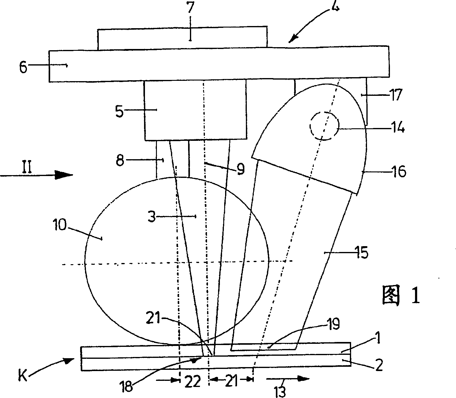
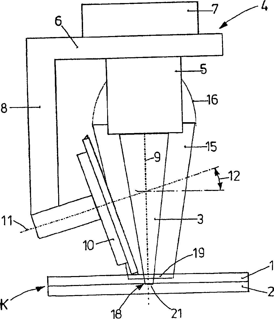
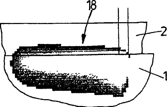
[0027] 1 and 2 show the edge profile K of two joined parts 1 , 2 to be welded. The two parts are joined together by laser irradiation, while the upper joining part 1 must transmit the laser welding beam 3 as much as possible, and the lower joining part 2 must absorb the laser welding beam 3 as much as possible. The rest of the laser irradiation welding is well known and needs no further introduction.

[0028] The laser welding beam 3 is guided from a stationary laser beam source to a focusing optics 5 via a fiber optics system via the processing head, indicated as a whole by 4 . For clarity, the laser source and fiber optics are omitted from the figure. The focusing optics 5 are located on a frame 6 of the processing head 4, which is flange-mounted via an adapter plate 7 with a force-measuring cell, eg on the manipulator arm of an industrial robot.

[0029] The clamping roller 10 is placed near the optical axis 9 of the laser welding beam 3 by means of a bracket 8; joints 1...


PUM


Abstract

The invention relates to a method and an apparatus for welding thermoplastic molded articles wherein additional simultaneous irradiation, in the welding area (18), of one of the join partners (1) will lead to a temperature increase of this join partner, occasioning process-reliable welding.

Description

technical field [0001] The invention relates to a method and a device for welding, in particular contour welding, of three-dimensional molded parts, which method and device comprise the features given in the preambles of claims 1 and 8 . Background technique [0002] The prior art has developed many laser beam welding methods for plastic parts. First, the two joining parts contact each other in the vicinity of the contour to be welded. A clamping device acts on the joint parts in the joint area to eliminate gaps between the joint parts that would negatively affect the welding result and to compensate for any shape tolerances. Finally, the laser welding beam irradiates the two joining parts in the welding area, as a result of which at least one of the joining parts melts, and the second part begins to melt by heat transfer, and at the same time, the final material of the two parts Lockingly connected. [0003] A typical example of this type of welding is laser penetration ...

Claims


Application Information

Patent Timeline
Patent Type & Authority Applications(China)
IPC IPC(8): B29C65/16B23K26/02B23K26/18B23K26/24B23K26/42B29C35/08B29C65/00
CPCB29C65/1616B29C66/9221B29C65/1635B23K26/246B29C65/1412B23K26/023B29C65/1696B29C66/81267B29C2035/0822B29C65/1606B29C65/1406B29C65/16B23K26/421B29C66/24B29C66/8362B29C65/72B29C65/1416B29C65/1467B29K2023/06B23K26/18B29C66/83411B29C66/024B29C65/1419B29C66/83417B29K2101/12B29C66/0242B29C65/1435B29C65/1458B29C65/1658B29C65/1664B29C66/1122B29C66/301B29C66/3474B29C66/41B29C66/43B29C66/45B29C66/54B29C66/71B29C66/73921B29C66/863B29C66/91411B29C66/9192B29C66/952B29C66/961B29K2995/0027B23K26/037B23K26/244B23K26/60B29C65/00B29K2055/02
Inventor A·霍夫曼S·希尔
Owner LPKF LASER & ELECTRONICS
Why Eureka
Try Eureka