Near-field calibrating method for high frequency surface wave radar uniform straight line array receiving channel

A uniform straight line, near-field technology, applied in the direction of radio wave reflection/re-radiation, radio wave measurement system, instrument, etc., can solve the problem that the phase error of the receiving channel has a great influence on the high-resolution algorithm, the estimation and calibration are difficult, and the channel corrects the phase Unbelievable estimated values ​​and other problems, to achieve the effects of reducing development costs and maintenance costs, good accuracy and robustness, and meeting real-time requirements

Inactive Publication Date: 2006-03-01
WUHAN UNIV
View PDF0 Cites 21 Cited by
  • Summary
  • Abstract
  • Description
  • Claims
  • Application Information

AI Technical Summary

Problems solved by technology

However, the application range and practical effect of this method are limited, and it is not suitable for sea areas without known fixed reflectors (such as islands), and is still affected by adverse factors such as noise interference, ship echo, and multipath effects.
[0007] Some people in the radio wave propagation laboratory of Wuhan University have also proposed that the calibration of the radar receiving channel can be realized by using the ocean echo, but some auxiliary antennas and auxiliary channels (the so-called nonlinear array) need to be added, but this not only increases the antenna footprint, Moreover, the original limited antenna aperture is sacrificed, the cost is high, and the cost is high
Moreover, when the ocean is fully used for calibration, the premise is that the ocean echo characteristics must satisfy the theoretical model assumed by the researcher, and the relationship between these theories and the actual model is unknown, and the channel correction, especially the phase estimate, is incredible.
Theory and practice show that the phase error of the receiving channel has the greatest impact on the high-resolution algorithm, and its estimation and calibration are also the most difficult

Method used


Image

  • Near-field calibrating method for high frequency surface wave radar uniform straight line array receiving channel
  • Near-field calibrating method for high frequency surface wave radar uniform straight line array receiving channel
  • Near-field calibrating method for high frequency surface wave radar uniform straight line array receiving channel

Examples


Embodiment Construction

[0028] The present invention will be described in more detail below in conjunction with the accompanying drawings and embodiments.

[0029] The key point of the present invention is to transform the channel correction problem into a parameter estimation problem by establishing a single-azimuth echo signal model received by a uniform linear array, and thereby obtain a relatively accurate channel mismatch estimation.

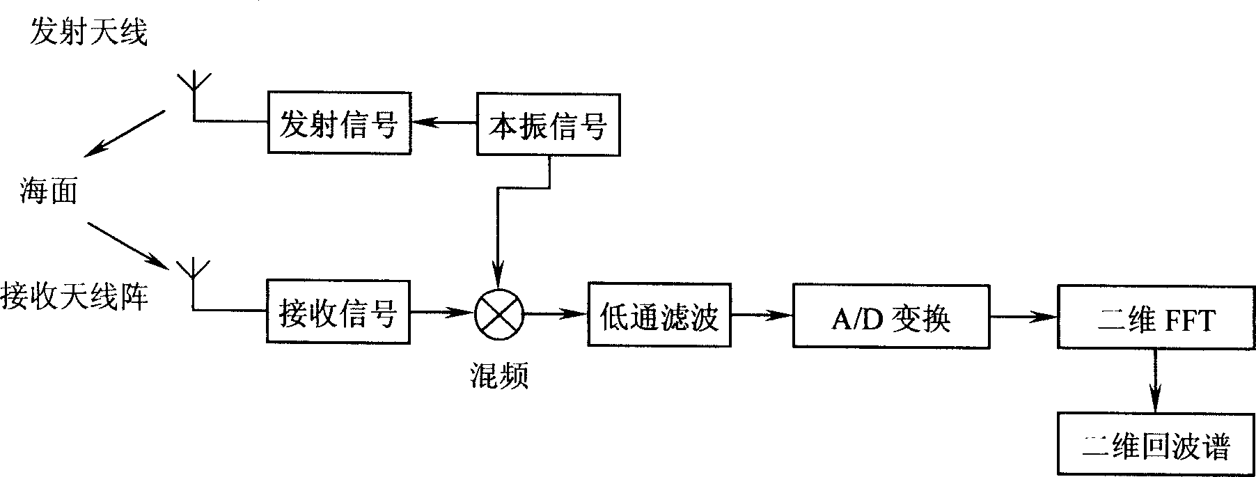
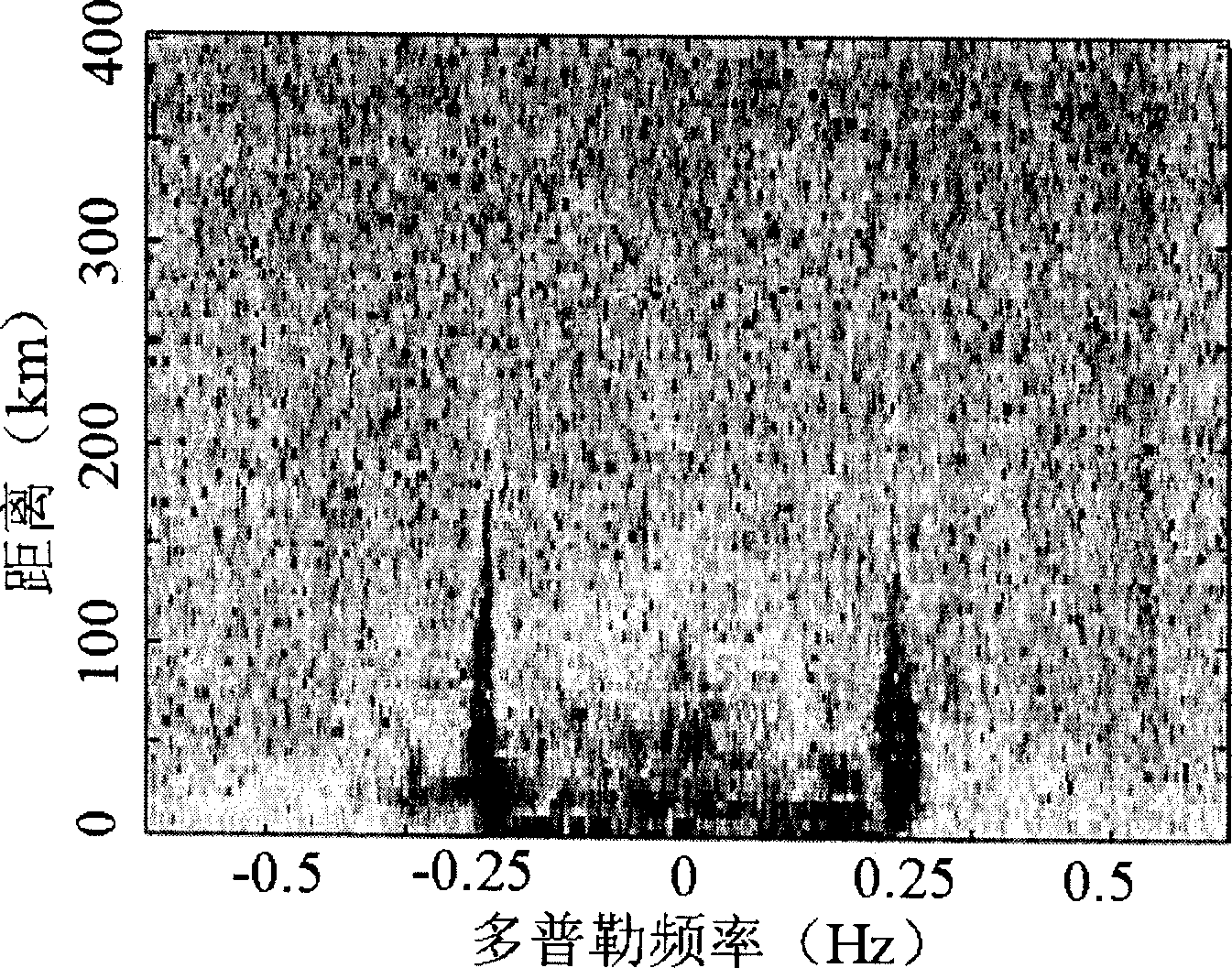
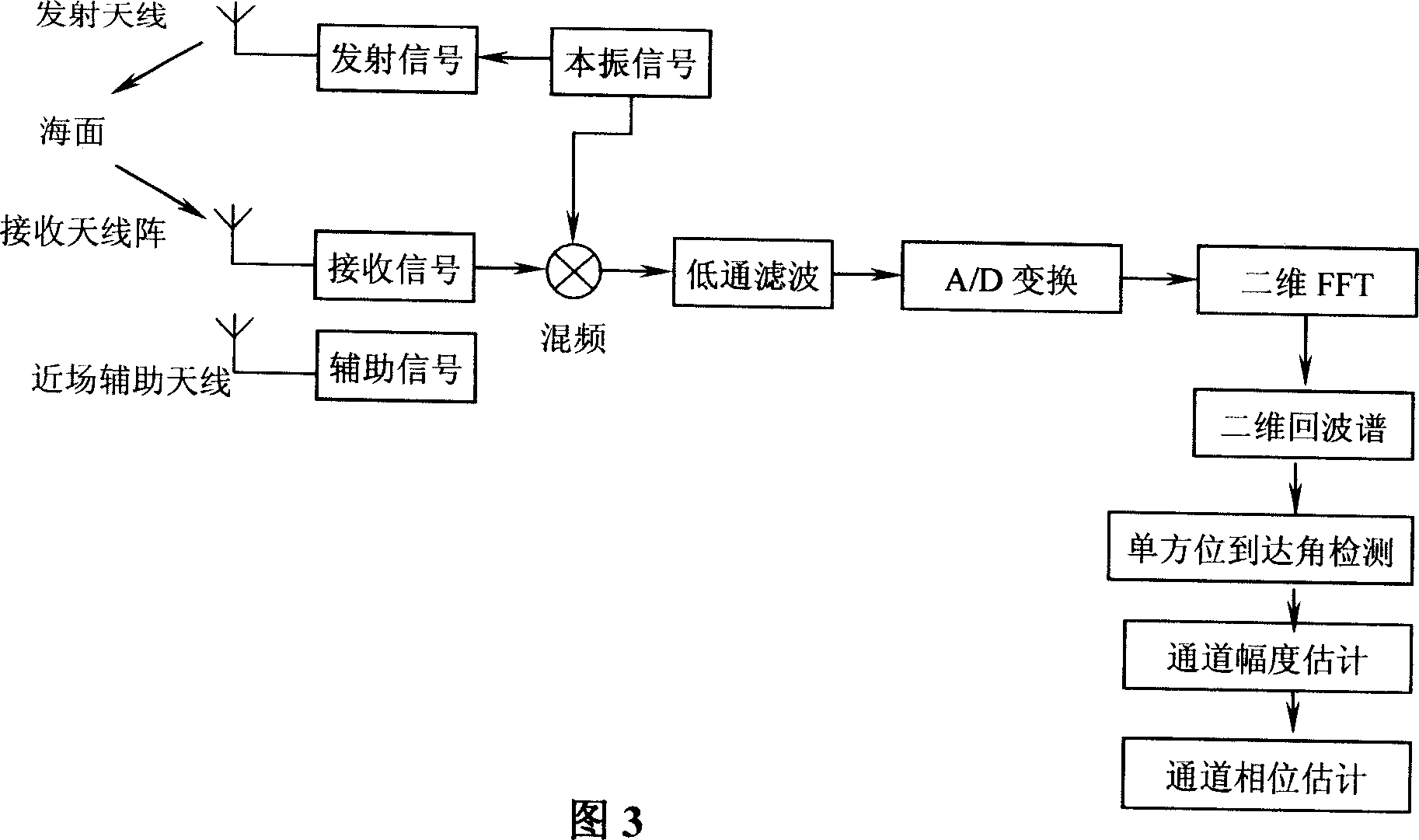
[0030] As shown in Figure 3, after the radiation signal of the transmitting antenna is scattered by the sea surface, the sea surface echo and the near-field auxiliary source signal enter the receiver, and the distance can be obtained by frequency mixing, low-pass filtering, A / D conversion and two-dimensional FFT - Doppler (velocity) two-dimensional echo spectrum. In the two-dimensional echo spectrum, a large number of ocean echoes received by the radar are separated according to distance and velocity, and scattered on many spectral points. When the coherent accum...


PUM


Abstract

The invented near-field correction method includes the following steps: utilizing position information of radar antenna array and high-frequency sea-state radar marine echo characteristics to detect marine echo with single-bearing arrival angle, and utilizing single-bearing arrival angle marine echo and multiple signal classification algorism to estimate channel amplitude mismatch factor to implement amplitude correction; utilizing near-field single auxiliary signal source set on the extended line of antenna array and utilizing amplitude-corrected single-bearing arrival angle near-field arrival wave signal, position information of array unit antenna, bearing information of near-field auxiliary source and multiple signal classification algorism to estimate and obtain mismatch factor of channel phase so as to implement phase correction.

Description

technical field [0001] The invention relates to a near-field correction method for a single auxiliary source in a receiving channel of a uniform linear antenna array of a high-frequency surface wave radar. Background technique [0002] High-frequency surface wave over-the-horizon radar utilizes the characteristics of small diffraction and propagation attenuation of vertically polarized high-frequency electromagnetic waves on the conductive ocean surface, and can over-the-horizon detect moving targets such as ships, aircraft, and missiles that appear below the line of sight at sea level. In addition, the high-frequency surface wave over-the-horizon radar uses the first-order and second-order scattering mechanisms of the ocean surface for high-frequency electromagnetic waves to extract ocean dynamic parameters such as wind field, wave field, and flow field from radar ocean echoes, which can realize Large-scale, high-precision and all-weather real-time monitoring of the marine ...

Claims


Application Information

Patent Timeline
Patent Type & Authority Applications(China)
IPC IPC(8): G01S7/40G01S13/02
Inventor 高火涛张小林
Owner WUHAN UNIV
Why Eureka
Try Eureka