Display device comprising a cathode ray tube
A technology of display equipment and electron beams, applied in the direction of color signal processing circuits, etc., can solve the problems of poor frequency response of video amplifiers, increased capacitive load of video amplifiers, expensive transistors, etc.
- Summary
- Abstract
- Description
- Claims
- Application Information
AI Technical Summary
Problems solved by technology
Method used
Image

Examples
Embodiment Construction
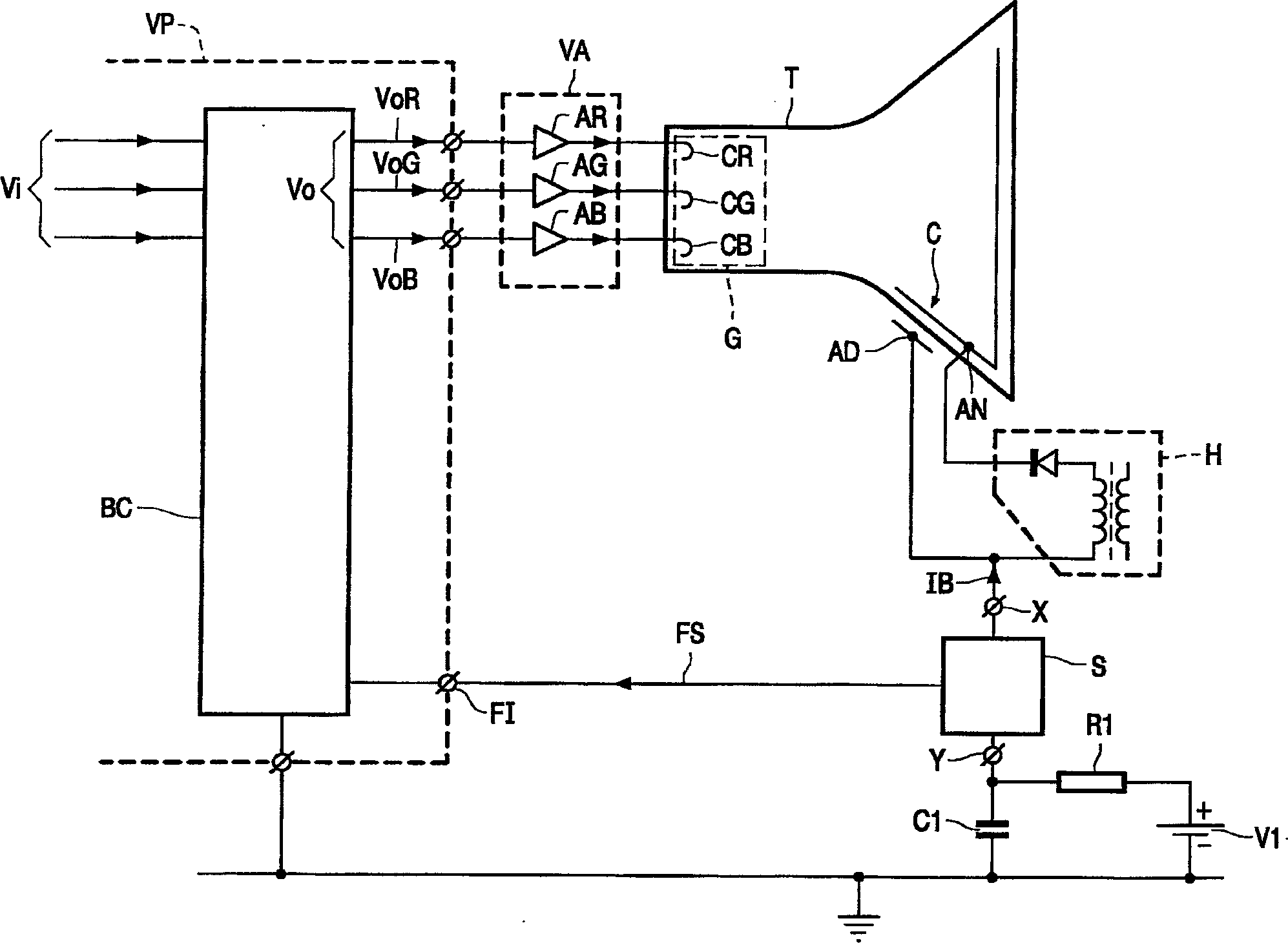
[0019] Such as figure 1 The shown display device has a cathode ray tube T, a video amplifier VA, a video processing circuit VP, a high voltage generator H, and a detection circuit S. The tube T has an electron gun (G) for generating at least one electron beam. The cathode ray tube T may be a monochrome tube whose electron gun G has one cathode or a color tube whose electron gun G has three cathodes G. exist figure 1 , a tube T is shown having a gun (G) comprising three cathodes CR, CG, CB for generating three electron beams corresponding eg to the colors red, green and blue. Tube T also has an internal high voltage capacitor C formed by a conductive layer at the inside of the tube connected to the anode AN of tube T and an outer conductive layer AD at the outside of the tube opposite the inner conductive layer. The video amplifier VA comprises three amplifier stages AR, AG, AB which receive corresponding color components VoR, VoG, VoB of the video signal Vo. The respective...
PUM
 Abstract
Description
Claims
Application Information