Micro-camera lens system

A miniature camera and lens technology, applied in the field of camera lens systems, can solve the problems of high cost and low imaging quality, and achieve the effects of easy processing, cost reduction, and large feature size

Active Publication Date: 2006-03-15
TSINGHUA UNIV +1
View PDF5 Cites 5 Cited by
  • Summary
  • Abstract
  • Description
  • Claims
  • Application Information

AI Technical Summary

Problems solved by technology

[0015] The technical problem to be solved by the present invention is to overcome the high cost and low imaging quality of the above micro-camera lens system, and provide a micro-camera lens system with low cost and good imaging quality

Method used


Image

  • Micro-camera lens system
  • Micro-camera lens system
  • Micro-camera lens system

Examples


no. 1 example

[0058] The miniature camera lens system meets the conditions of Table 1, Table 2 and Table 3:

[0059] f=6.00mm T=9.64mm FNo=2.8 2ω=40°

[0060]

[0061] Diffraction phase coefficient

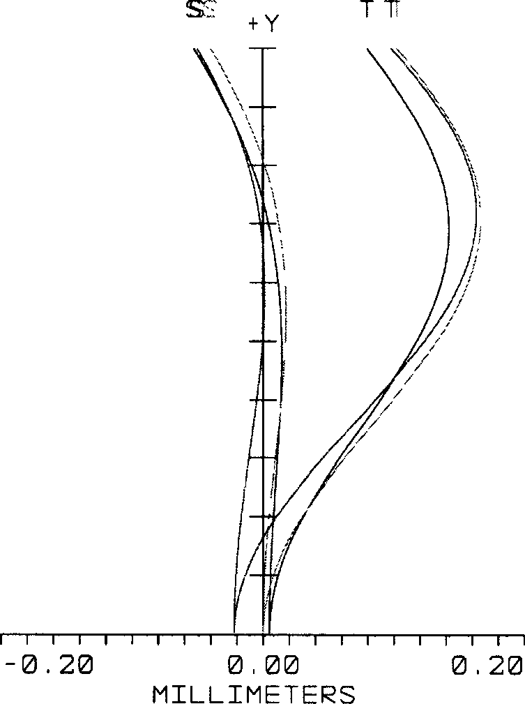
[0062] In the miniature camera lens system of the first embodiment, its curvature of field and distortion, on-axis spherical aberration and chromatic aberration are respectively as follows Figure 3A to Figure 4 shown. in Figure 3A and Figure 3B represent the field curvature curve and the distortion curve, respectively. It can be seen from the figure that the above-mentioned curvature of field, distortion, and on-axis spherical aberration and chromatic aberration can be well corrected.

no. 2 example

[0064] The miniature camera lens system meets the conditions of Table 4, Table 5 and Table 6:

[0065] f=6.00mm T=9.60mm FNo=ω=40°

[0066]

[0067] Diffraction phase coefficient

[0068] In the micro camera lens system of the second embodiment, its curvature of field and distortion, on-axis point spherical aberration and chromatic aberration are respectively as follows Figure 5A to Figure 6 shown. in Figure 5A and Figure 5B represent the field curvature curve and the distortion curve, respectively. It can be seen from the figure that the above-mentioned curvature of field, distortion, and on-axis spherical aberration and chromatic aberration can be well corrected.

no. 3 example

[0070] The miniature camera lens system meets the conditions of Table 7, Table 8 and Table 9:

[0071] f=5.00mm T=8.07mm FNo=2.8 ω=50°

[0072]

[0073] Diffraction phase coefficient

[0074] In the miniature camera lens system of the third embodiment, its curvature of field and distortion, on-axis point spherical aberration and chromatic aberration are respectively as follows Figure 7A to Figure 8 shown. in Figure 7A and Figure 7B represent the field curvature curve and the distortion curve, respectively. It can be seen from the figure that the above-mentioned curvature of field, distortion, and on-axis spherical aberration and chromatic aberration can be well corrected.


PUM


Abstract

A micro video camera lens system consists of shutter and meniscus shaped thick lens with its concave surface towards to objective side and its convex surface towards to imaging surface. It is featured as using no spherical surface as surface towards to objective side and using convex surface with diffraction grating as surface towards to imaging surface, applying condition formula of ( 1 ) 0.1ú“R2 / R1 ú“0.5 for said system whether R1 ¿C curvity of surface top near to objective side and R2 ¿C curvity of surface top near to imaging surface.

Description

【Technical field】 [0001] The invention relates to a camera lens system, in particular to a miniature camera lens system suitable for miniature camera elements such as mobile phones and PC cameras. 【Background technique】 [0002] In recent years, with the development of multimedia, there is an increasing demand for image pickup devices using solid-state imaging devices such as CCD (Charged Coupled Device) or CMOS (Complementary Metal Oxide Semiconductor) mounted on laptop computers, videophones, and mobile phones. Big. And this increased demand itself requires further miniaturization and light weight of the lens system. [0003] On the other hand, due to the improvement of the process technology of these solid-state imaging devices such as CCD or CMOS, imaging devices with each pixel only a few microns in size have been produced, which makes the system miniaturized and improves the resolution requirements of the camera lens. Therefore, providing a lens system with miniaturi...

Claims


Application Information

Patent Timeline
Patent Type & Authority Applications(China)
IPC IPC(8): G02B13/18G02B1/04H04N5/225
CPCG02B13/18G02B13/0025G02B13/0055
Inventor 曾吉勇严瑛白金国藩王民强王卓
Owner TSINGHUA UNIV
Why Eureka
Try Eureka