Motor and devive using this

A technology of motors and armatures, applied in the field of motors, can solve problems such as ineffective use of electricity

Inactive Publication Date: 2006-03-15
VENERA LAB CO LTD
View PDF1 Cites 5 Cited by
  • Summary
  • Abstract
  • Description
  • Claims
  • Application Information

AI Technical Summary

Problems solved by technology

Therefore, in the conventional permanent magnet type DC motor, there is a problem that the electric power applied to the armature cannot be effectively used.

Method used


Image

  • Motor and devive using this
  • Motor and devive using this
  • Motor and devive using this

Examples


Embodiment 1

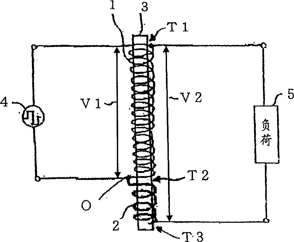
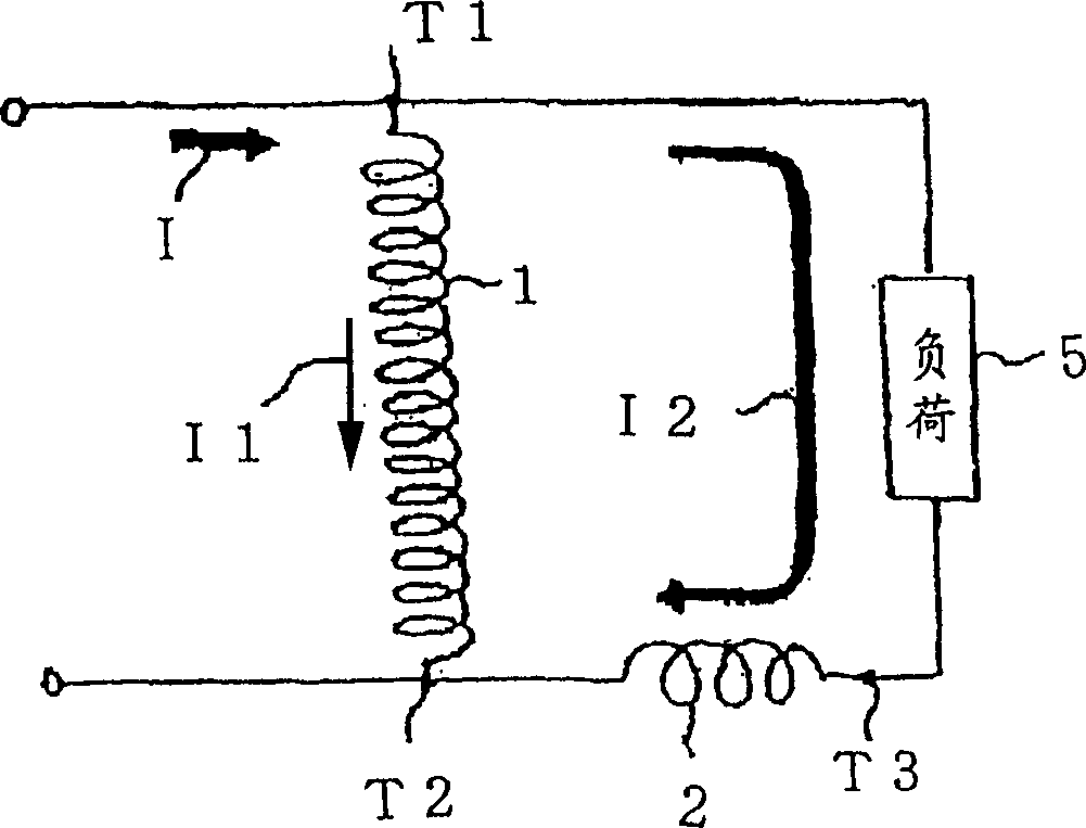
[0121] First, Embodiment 1 of the present invention will be described. figure 2 It is a basic circuit diagram showing the winding structure of two coils 1, 2 wound on a linear iron core used in the linear motor of Embodiment 1 of the present invention. In this embodiment, the coil 1 and the coil 2 are wound around the iron core 3 in the same direction, and the coil 1 and the coil 2 are alternately arranged and connected in parallel. image 3 is equivalent to figure 2 The circuit diagram of coil 1 and coil 2 in the figure 1 The currents I1, I2 flowing in the windings are shown. exist figure 2 Among them, the iron core 3 is a laminated electromagnetic steel sheet having a rod-shaped structure with the same cross-sectional area. Coils 1, 2 have different resistances. For example, on the core 3, a coil 1 made of thin copper wire with a large number of windings and a large resistance value and a coil 2 made of thick copper wire with a small number of windings and wound in t...

Embodiment 2

[0132] Next, Embodiment 2 of the present invention will be described. In the above-mentioned embodiment 1, a linear motor is realized, but in the present embodiment 2, a rotary motor using the above-mentioned transformer can be realized.

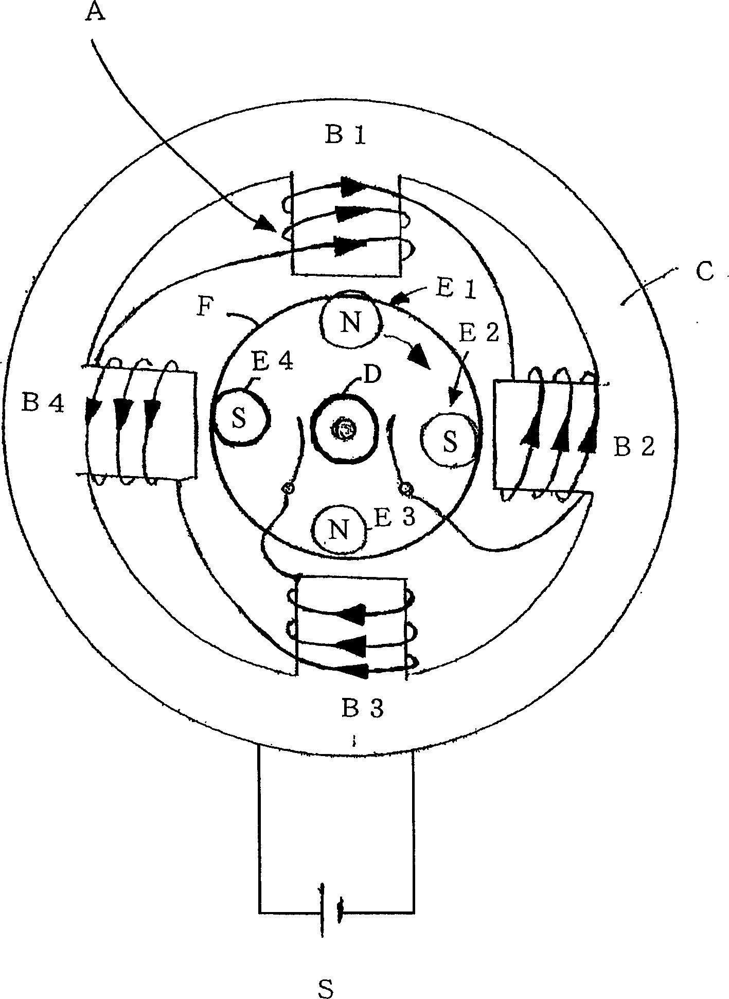
[0133] Figure 6 It is an assembly diagram of a rotating electric machine 20 composed of a permanent magnet rotor 21 and an annular magnetic circuit armature 24 as a second embodiment of the present invention. In this embodiment, the annular magnetic circuit armature 24 is annular, formed by the circular iron core 23 and the rotor, and is circular. In this example, if Figure 7 As shown, three coils 1 a to 1 c and three coils 2 a to 2 c are alternately wound around the circumference of the iron core 23 . Such as Figure 5 The winding method of coils 1a~1c is series winding, and the winding method of coils 2a~2c is parallel winding. In the embodiment, the coils 1a to 1c are thinner, have more windings than the coils 2a to 2c, and have hi...

Embodiment 3

[0152] Figure 12 It is an assembly diagram for explaining Embodiment 3 of the present invention. The constitution of the present embodiment 3 is that, on the basis of the structure of the embodiment 2, it further has the power generation function, and supplements the lost electric energy such as copper loss and iron loss of the commutator 26 and the annular magnetic circuit armature 24 . The yoke 25 is positioned above the air core coil, the disc is supported by the shoulder 21c of the shaft 21b, and the commutator 26 is supported by the disc. The yoke 25 has the same inclination and size as the permanent magnet rotor 21 and is parallel thereto. The yoke is, for example, iron. While the yoke 25 is rotated by the permanent magnet rotor 21, an applied torque is generated in the yoke by eddy current. Figure 12 It is an independent figure of the motor of Example 3 of this invention. in addition, Figure 13 to represent Figure 12 Diagram showing the positional relationship...


PUM


Abstract

A motor comprising an annular magnetic path armature (24) having coils (1a-1c) that are wound in the same direction around an armature iron core forming an annular magnetic path, are high in direct-current resistance, and are connected in series, and coils (2a-2c) that are wound in the same direction, are lower in direct-current resistance and smaller in the number of windings than the coils (1a-1c), form magnetic domains of the same length, and connected in series or in parallel, the coils (1a-1c) and the coils (2a-2c) being disposed alternately, and a permanent magnet rotor (21) provided thereon with permanent magnets (22), having the samenumber of magnetic domains and unlike magnetic poles, disposed at an equal interval and alternately in the peripheral direction of the vicinity of the inner periphery of the annular magnetic path armature (24), wherein power rectified and commutated to the series-connected coils (1a-1c) via a commutator (26) is input to between terminals (12, 13), and a load is connected between terminals (12, 11) to which parallel-connected coils (2a, -2c) and coils (1a-1c) are series-connected.

Description

technical field [0001] The present invention relates to a motor and a device using the motor, capable of efficiently driving a motor having an armature and a permanent magnet rotor. Background technique [0002] As a conventionally known DC motor, there is a motor disclosed in JP-A-8-126279, figure 1 It is a schematic diagram showing a representative permanent magnet type DC motor. Such as figure 1 As shown, the coil A is wound around most of the gears B1 , B2 , B3 , B4 extending radially inwardly from the annular stator C. Coil A is connected to power S. The electric current supplied by the power supply S generates a magnetic field through the gears B1-B4. A rectifier (commutator) D is electrically connected to the power source S and the coil A, and alternately supplies DC current supplied from the coil power source. Coils A are directly wound around the respective gears B1 to B4 alternately so that the polarities of the magnetic field are in opposite directions to the...

Claims


Application Information

Patent Timeline
Patent Type & Authority Applications(China)
IPC IPC(8): H02K29/00H02K1/27H02K3/28
CPCY02T10/641
Inventor 水岛保男
Owner VENERA LAB CO LTD
Why Eureka
Try Eureka