

Multiple segment steam stripping method for catalyst
A technology for catalysts and catalysts to be produced, applied in chemical instruments and methods, catalyst regeneration/reactivation, physical/chemical process catalysts, etc., can solve the problem that the overflow multi-stage stripping method has not yet been reported, and the cooling and heating methods are difficult to achieve. and control, the improvement of stripping effect is limited, etc.
- Summary
- Abstract
- Description
- Claims
- Application Information
AI Technical Summary
Problems solved by technology
Method used
Image

Examples
Embodiment approach 1
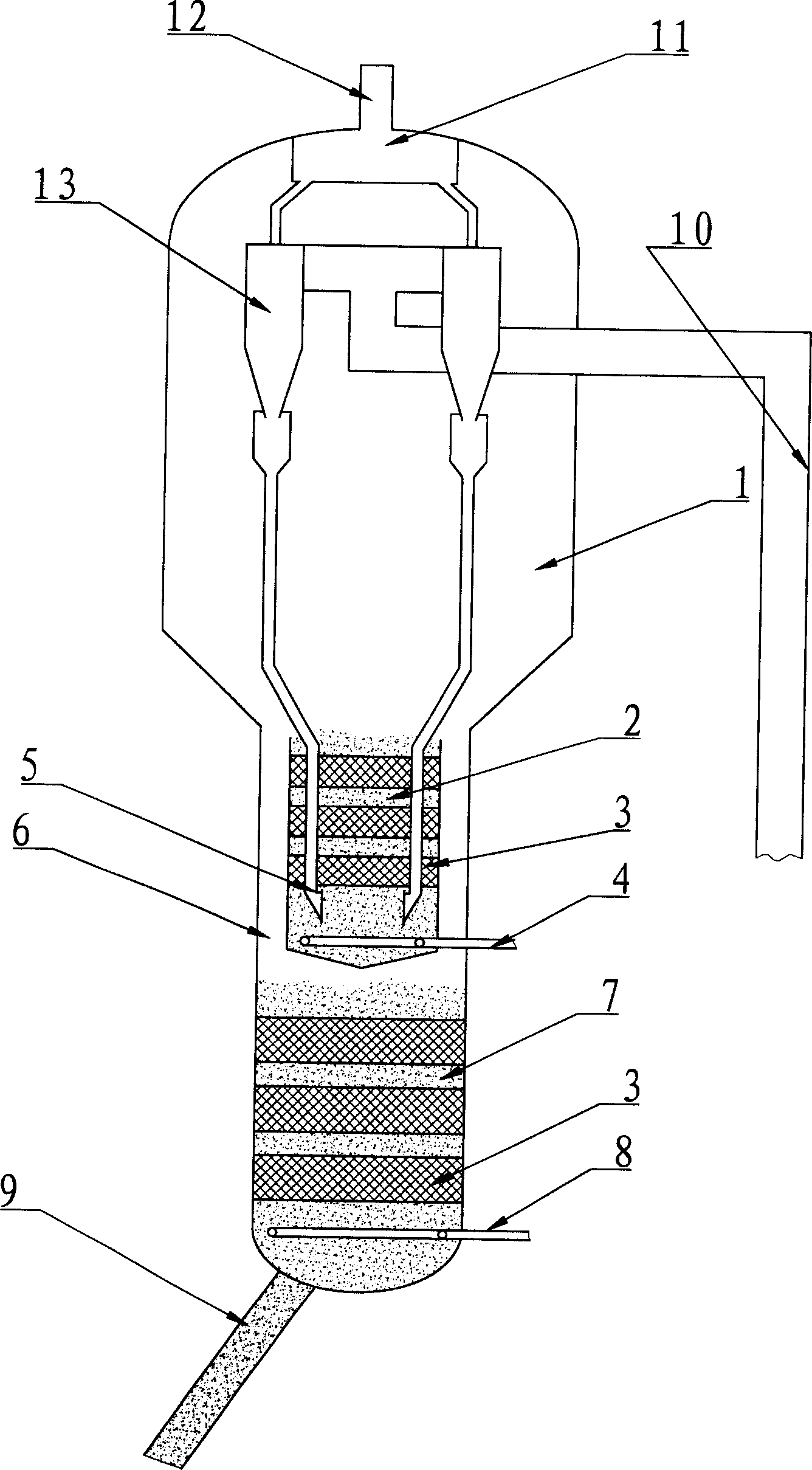
[0024] Implementation mode one: such as figure 1 As shown, the reacted oil and gas and the spent catalyst from the riser reactor 10 (part of) enter the cyclone 13 to initially separate the oil and gas and the spent catalyst. After the oil and gas from different cyclones are collected in the settler plenum 11, they enter the subsequent fractionation system through the pipeline 12 for subsequent separation of products. The spent catalyst separated by the cyclone separator 13 enters the bottom of the first stripping section 2 through the material legs of the cyclone separator, and the stripping steam is distributed as evenly as possible in the first stripping section 2 through the distributor 4. Under the action of the stripping steam, the catalyst flows from the bottom of the first stripping section 2 through the multilayer stripping packing 3 to the top of the stripping section, and overflows through the top edge of the stripping section, passing through the ring The channel 6 flo...
Embodiment approach 2
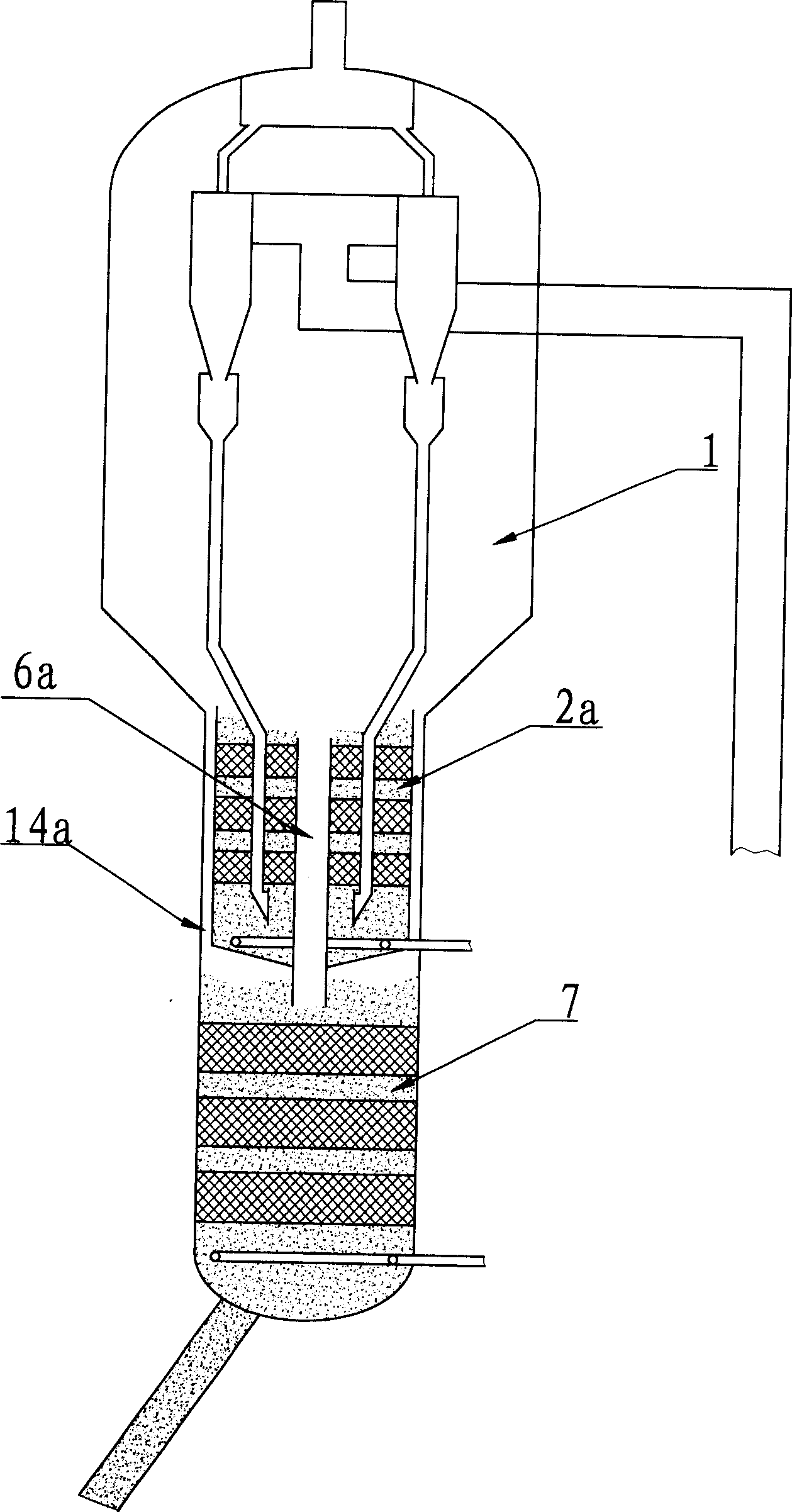
[0031] Implementation mode two: such as figure 2 As shown, the stripper includes two stripping sections, which are figure 1 The difference of the stripper shown is that the catalyst overflowed from the first stripping section 2a enters the second stripping section 7 from the central discharging pipe 6a, and the oil and gas stripped from the second stripping section The and stripping steam enters the dilute phase space of the settler 1 along the annular channel 14a. To achieve this, the outer edge of the top of the first stripping section 2a is 50-400mm higher than the top of the central discharge pipe 6a, so as to ensure that the catalyst enters the second stripping section from the central discharge pipe. It will not enter into the annular passage 14a for lifting. Here, the cross-sectional area of the central discharge pipe accounts for 5-20% of the cross-sectional area of the stripper, the cross-sectional area of the annular channel accounts for 0.5-10% of the cross-sect...
Embodiment approach 3
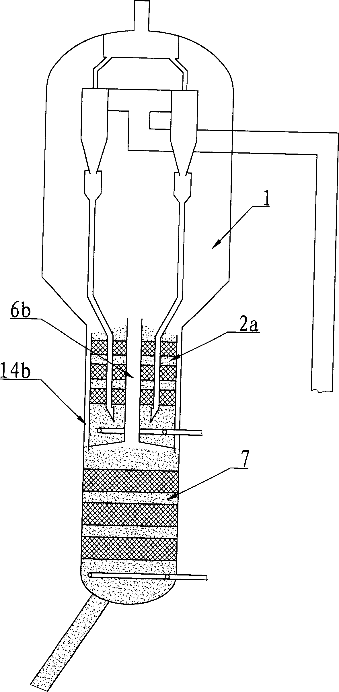
[0032] Implementation mode three: such as image 3 As shown, the stripping method is the same as figure 2 The difference of the method shown is that the catalyst overflowed from the first stripping section 2b overflows from the outer side wall of the top of the stripping section, and then is transported to the second stripping section 7 through the annular channel 14b; and The oil and gas and stripping steam stripped from the second stripping section enter the dilute phase space of the settler 1 from the central riser pipe 6b. To achieve this, the outer edge of the top of the first stripping section 2b is 50-400mm lower than the top of the central riser 6b, so that the catalyst can enter the second stripping section from the annular discharge channel 14b on the side wall. It will not enter the central ascending duct. Here, the cross-sectional area of the annular channel 14b accounts for 5-20% of the cross-sectional area of the stripper, the bottom of the annular channel 14b e...
PUM
 Abstract
Description
Claims
Application Information