

Impellor used for centrifugal pump and centrifugal type fan
The technology of a centrifugal fan and a centrifugal pump is applied to the impeller. In the field, it can solve the problems of low operating efficiency, increased friction surface, and consumption of useless work, so as to achieve the effects of improving operating efficiency, increasing vacuum degree, and accelerating flow velocity.
- Summary
- Abstract
- Description
- Claims
- Application Information
AI Technical Summary
Problems solved by technology
Method used
Image

Examples
Embodiment Construction
[0025] The present invention will be described in further detail below in conjunction with the accompanying drawings.
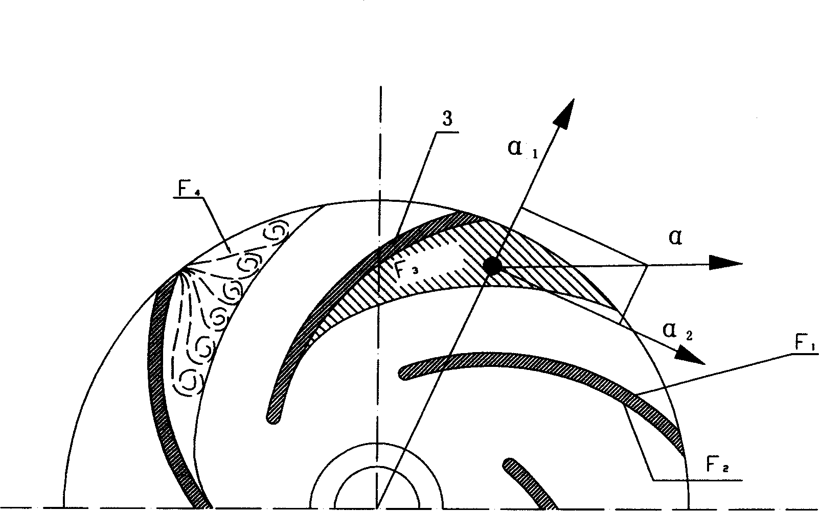
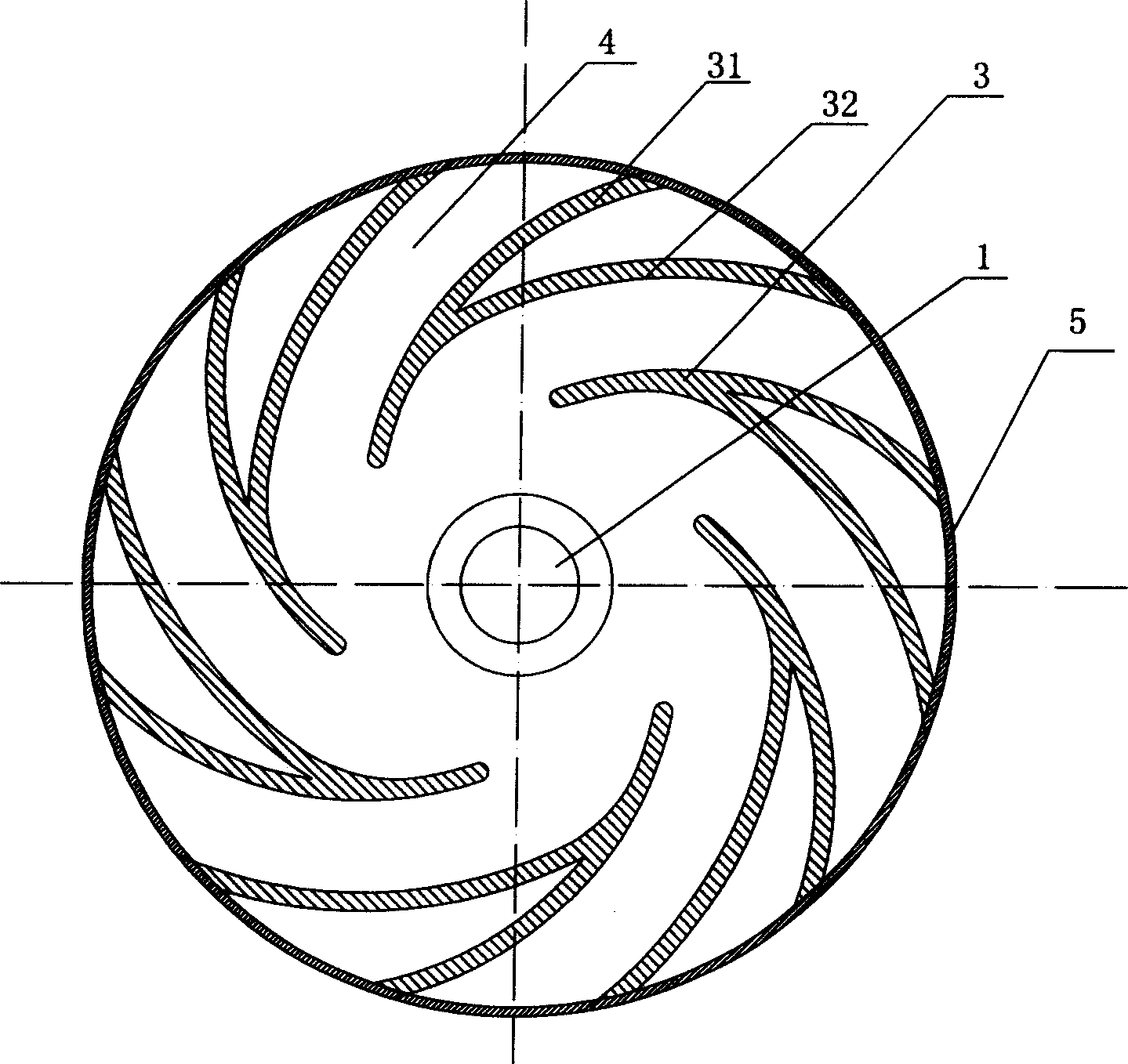
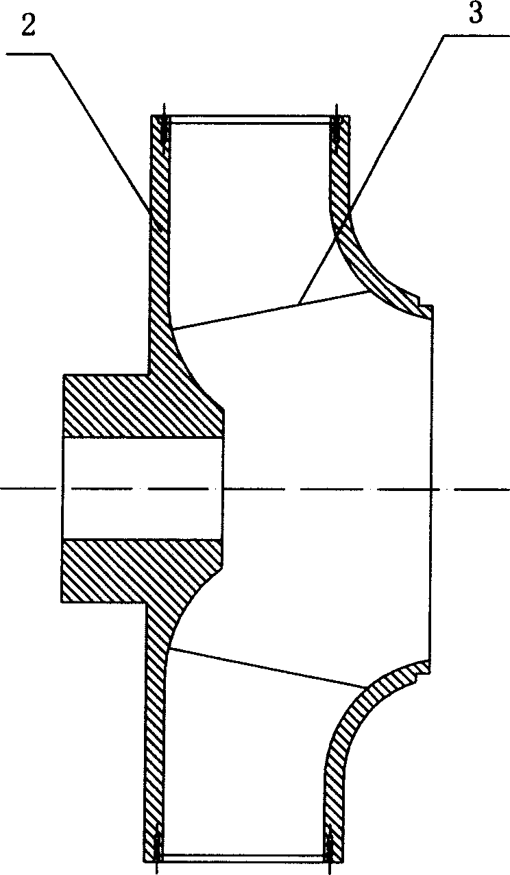
[0026] Such as figure 2 and image 3 As shown, the impeller used for centrifugal pumps and centrifugal fans of the present invention includes a wheel housing 1, a web 2, and two or more blades 3 installed on the web 2, and between adjacent blades 3 A flow channel 4 is formed between them. The blade 3 is composed of a main blade 31 and an auxiliary blade 32. The main blade 31 and the auxiliary blade 32 are overlapped at the small radius end of the impeller. As the radius of the impeller increases, the main blade 31 and the auxiliary blade The distance between 32 gradually widens, and the main blade 31 and auxiliary blade 32 are connected by a sealing plate 5 at the largest radius of the impeller. In a preferred embodiment, the overlapping thickness of the main blade 31 and the auxiliary blade 32 at the small radius end of the impeller is equal to the thickn...
PUM
 Abstract
Description
Claims
Application Information