Vapor deposition apparatus

A vapor deposition and gas flow channel technology, applied in gaseous chemical plating, metal material coating process, coating, etc., can solve problems affecting crystal growth, uneven thickness, uneven crystallinity, etc.

Inactive Publication Date: 2006-05-03
SHARP KK +1
View PDF2 Cites 6 Cited by
  • Summary
  • Abstract
  • Description
  • Claims
  • Application Information

AI Technical Summary

Problems solved by technology

As a result, the crystallinity becomes non-uniform on the crystal film face and the thickness becomes non-uniform on the crystal film face
Thus, the change in the amount of outflow gas seriously affects the crystal growth

Method used


Image

  • Vapor deposition apparatus
  • Vapor deposition apparatus
  • Vapor deposition apparatus

Examples


Embodiment approach 1

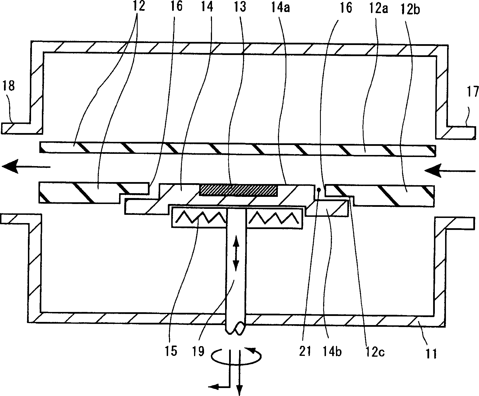
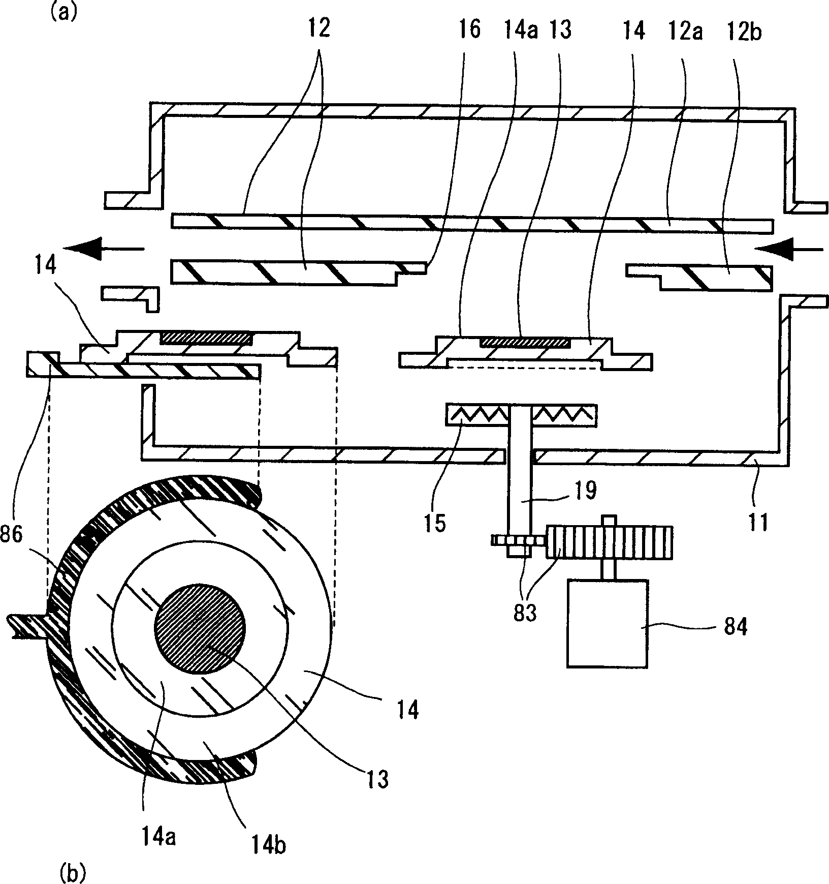
[0048] figure 1 is a cross-sectional view of the vapor deposition apparatus of Embodiment 1. This vapor deposition apparatus has, in a reaction chamber 11, a gas flow path 12 for efficiently supplying a source gas onto a substrate 13, a substrate holding member 14 for holding the substrate 13, and a heating substrate holding member 14 in a reaction chamber 11 as in a conventional apparatus. Heater 15. The airflow channel 12 has an upper wall 12a and a lower wall 12b. The source gas flows from the gas supply hole 17 to the gas outlet 18 in parallel to the substrate 13 through the gas flow channel 12 . The lower wall 12 b of the air flow passage 12 has an opening portion 16 . The substrate holding surface 14 a of the substrate holding member 14 is fitted into the opening portion 16 while forming a space 21 between the opening portion 16 and the substrate holding member 14 . The substrate 13 and the substrate holding surface 14 a of the substrate holding member 14 are in con...

Embodiment approach 2

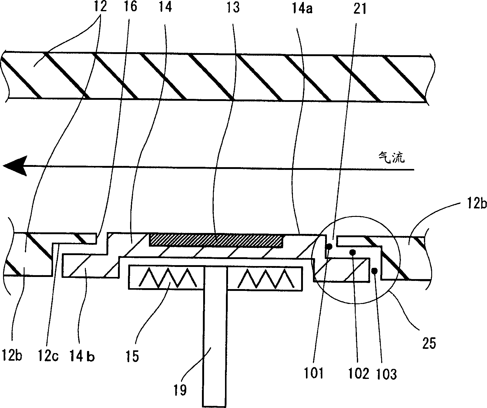
[0062] Figure 6is a partially enlarged cross-sectional view assembling a gas flow channel and a substrate holding member according to Embodiment 2 of the present invention. As shown, in this embodiment, the means for reducing gas leakage consists of a laterally protruding edge 14b from the side wall of the substrate holding member 14 when the substrate holding face 14a of the substrate holding member 14 is in the loading opening. In the state in the portion 16, a space 21 is formed between the edge 14b of the air flow channel 12 and the lower wall 12b at the same time. The lower wall 12b of the airflow channel 12 is of conventional design. That is, only the disc-shaped substrate holding member 14 provided with the edge 14b disposed at its periphery forming the hole structure 25 defined by the opening portion 16 of the gas flow path 12 and the substrate holding member 14 is provided. In this case, the space 21 formed between the hole portion 16 of the gas flow path 12 and th...


PUM


Abstract

A vapor deposition apparatus of the present invention has a substrate holding member having a substrate holding surface on which a substrate is held, and a gas flow path for supplying a source gas onto the substrate. The airflow channel has an upper wall and a lower wall. The opening part is arranged on the lower wall of the airflow channel. The substrate holding surface of the substrate holding member fits into the opening portion while forming a space between the substrate holding surface and the opening portion. A means for reducing gas leakage through a space between an aperture portion and a substrate holding member is provided. With this structure, since means for reducing gas leakage through the space between the opening portion and the substrate holding member is provided, the conductance of gas outflow is reduced, which in turn reduces variation in the amount of outflow gas. This leads to high-yield production of nitride semiconductor elements with long lifetime and high luminous efficiency.

Description

technical field [0001] The present invention relates generally to vapor deposition apparatus, and in particular to an improved vapor deposition apparatus for high yield production of nitride semiconductor devices. Background technique [0002] Nitride-based III-V compound semiconductor crystals represented by GaN, InGaN, AlGaN, AlInGaN, etc. have direct transition band gaps and are expected to be applied to semiconductor lasers. InGaN hybrid crystals are capable of red to ultraviolet emission and are therefore of particular interest as short-wave materials. These crystals have been put into practical use as light-emitting diode elements having a wavelength range from ultraviolet light to green light, and as blue-violet laser diode elements. Typically, these elements are produced by metal organic chemical vapor deposition (MOCVD) using a CVD apparatus. Specifically, GaN-type, InGaN-type, AlGaN-type, InGaNP-type, InGaNAs-type, and InGaAlN-type nitride semiconductor thin film...

Claims


Application Information

Patent Timeline
Patent Type & Authority Applications(China)
IPC IPC(8): C23C16/00C23C16/54
CPCC23C16/455C23C16/54
Inventor 山田英司汤浅贵之荒木正浩阿久津仲男
Owner SHARP KK
Why Eureka
Try Eureka