Drive train for a mobile vehicle and method for controlling said drive train

A transmission line and vehicle technology, applied in the direction of transmission control, transmission, control devices, etc., can solve problems such as speed difficulties, and achieve the effect of reducing the burden

Inactive Publication Date: 2006-05-03
ZF FRIEDRICHSHAFEN AG
View PDF1 Cites 3 Cited by
  • Summary
  • Abstract
  • Description
  • Claims
  • Application Information

AI Technical Summary

Problems solved by technology

Because the driver is also operating the working hydraulics and, if necessary, the steeri

Method used


Image

  • Drive train for a mobile vehicle and method for controlling said drive train

Examples


Embodiment Construction

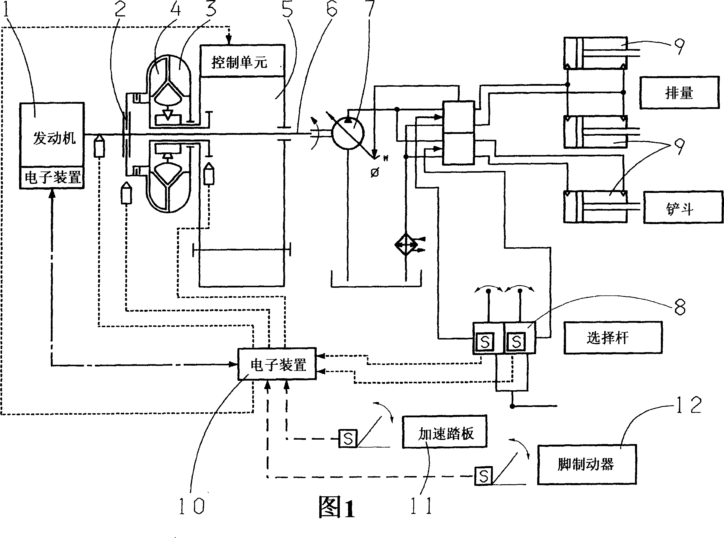
[0016] The single figure shows an engine 1 , which drives a pump impeller 3 of a hydrodynamic torque converter via a primary clutch 2 . The turbine 4 drives the load switching transmission 5 . The engine 1 also drives an auxiliary transmission 6 which drives a hydraulic pump 7 of the working hydraulic system. By actuating the selector lever 8 , the volume flow of the hydraulic pump 7 is delivered to a consumer 9 , for example a bucket of a wheel loader. The hydraulic pump 7 may be a load-sensing pump (Load-Sensing-Pump). The electronic control unit 10 receives signals from the selector lever 8 as well as the accelerator pedal 11 and the foot brake pedal 12 . The electronic control unit also receives sensor signals of engine 1 speed, clutch 2 operation and load switching transmission 5 speed. If the driving speed is adjusted with the accelerator pedal 11 and the selector lever 8 is actuated simultaneously, the electronic control unit 10 regulates the engine 1 to a minimum sp...


PUM


Abstract

In a transmission line for a working machine, in particular a wheel loader, the travel speed is preselected via the accelerator pedal (11) and the working hydraulics via the selector lever (8), wherein the signal is fed to An electronic control unit (10) which controls the transmission motor (1) and the clutch (2) arranged between the transmission motor (1) and the pump impeller (3) of the hydrodynamic torque converter in such a way that the auxiliary transmission The device (6) provides sufficient rotation speed for the pump (7) of the working hydraulic system and does not exceed the preselected travel speed.

Description

technical field [0001] The invention relates to a transmission line of a mobile vehicle of the type defined in detail in the preamble of claim 1 . Background technique [0002] Drive lines according to classification are used in particular on work machines such as wheel loaders, graders or stackers, for example. In this case, the engine drives the drive wheels of the vehicle through a hydrodynamic torque converter and a downstream load switching transmission. The engine also drives the auxiliary drive for the hydraulic pumps of the working hydraulic system. If the driver intends, for example, to lift the bucket of a wheel loader and slowly approach the truck, he simultaneously actuates the foot brake and the accelerator pedal in order to increase the rotational speed of the hydraulic pump engine and reduce the travel speed by means of the foot brake. In this case the power input into the hydrodynamic torque converter is converted into heat energy. [0003] DE 195 21 458 A...

Claims


Application Information

Patent Timeline
IPC IPC(8): E02F9/22B60K25/00B60W10/02B60W10/04B60W10/06B60W30/18G06G1/00
CPCB60W10/02B60W10/06B60W10/30B60W30/18B60W2510/0225B60W2540/10B60W2540/12B60W2540/16E02F9/2253F16H2045/002F16H2061/0234B60W10/04B60W10/103B60W30/1819E02F9/20B60K25/00
Inventor 贝恩德·奥曼
Owner ZF FRIEDRICHSHAFEN AG
Why Eureka
Try Eureka