Matching circuit between pulse power source and capacitive load

A technology of pulse power supply and capacitive load, applied in the field of electrical engineering, can solve the problems of reduced pulse voltage rise rate, unfavorable rise rate of pulse power application effect, etc.

Inactive Publication Date: 2006-05-24
DALIAN UNIV OF TECH
View PDF0 Cites 4 Cited by
  • Summary
  • Abstract
  • Description
  • Claims
  • Application Information

AI Technical Summary

Problems solved by technology

Although this form of matching circuit can suppress the oscillation of the pulse voltage on the capacitive load, it also leads to a significant decrease in the rate of rise of the pulse voltage on the capacitive load. In many cases, reducing the rate of rise of the pulse voltage is not conducive to pulse The application effect of the power supply in the corresponding process, such as in the pulse bias arc ion plating process, in order to obtain a good coating effect, it is required to provide a negative pulse with a rising rate as high as possible and almost no oscillation for the capacitive load of arc ion plating bias

Method used


Image

  • Matching circuit between pulse power source and capacitive load
  • Matching circuit between pulse power source and capacitive load
  • Matching circuit between pulse power source and capacitive load

Examples


Embodiment Construction

[0018] Below in conjunction with accompanying drawing, describe preferred embodiment of the present invention in detail.

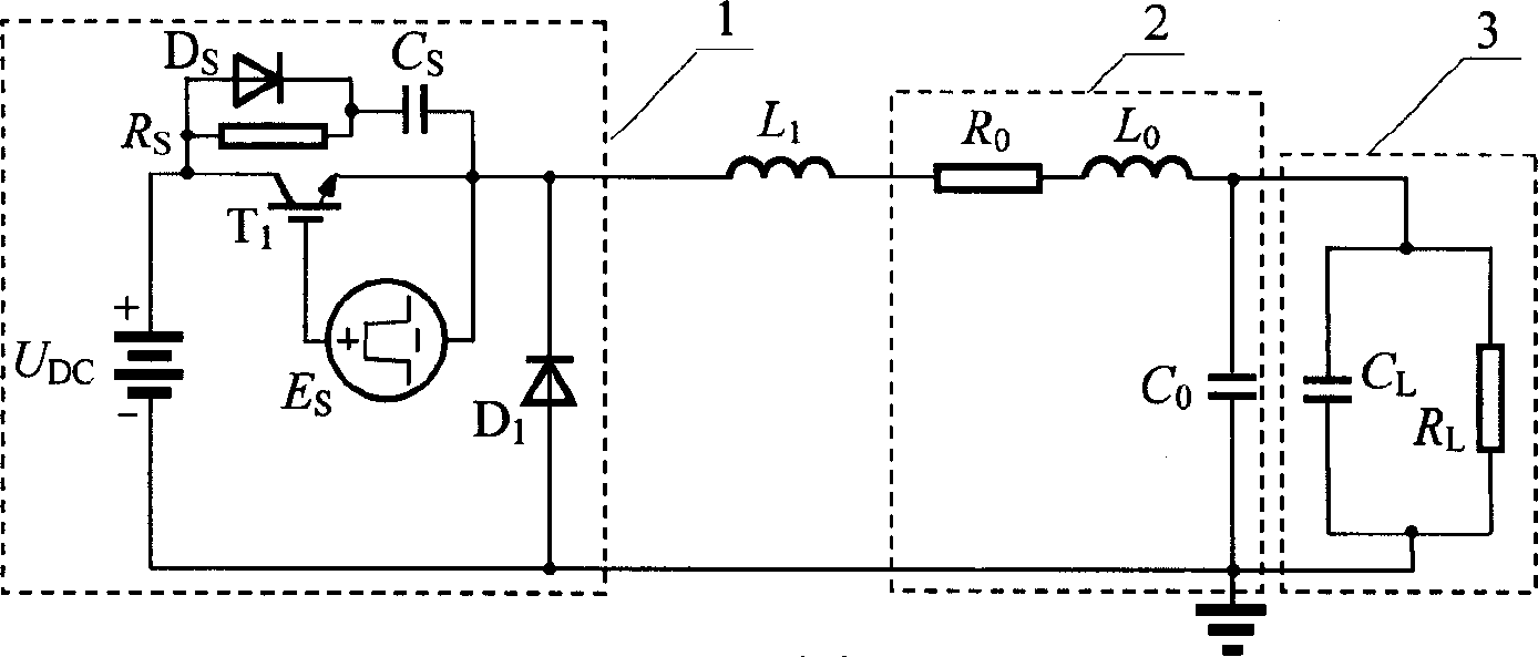
[0019] exist figure 1 In, DC power supply U DC , Power switch tube T 1 , pulse signal source E s , Diode D 1 and resistance R s , Diode D s , capacitance C s Constitutes the equivalent circuit of pulse power supply 1; resistance R 0 , inductance L 0 and capacitance C 0 Constitute the equivalent circuit of the coaxial cable 2 that transmits the pulse power between the pulse power supply and the capacitive load; the capacitance C L and resistor R L The equivalent circuit of the capacitive load 3 is formed, because in many cases, the capacitive load can be equivalent to a unit in which the capacitance and the resistance are connected in parallel in the circuit (such as arc ion plating load, gas laser load, etc., in addition, even if A capacitor, due to the existence of its leakage current, can also be equivalent to a unit in which the capacitor and...


PUM


Abstract

Being composed of inductance, capacitance and resistance, the matching circuit through coaxial cable is connected between output end of electrical pulse source and condensive load. Characters are that the matching circuit includes resistance-capacitance (CR) branch composed of cascaded CR, an inductance branch. The inductance branch and CR branch are connected in parallel. Parameters of inductance, capacitance and resistance in the matching circuit satisfies frequency response characteristic of ratio (u2/u1) between pulse voltage (u2) on condensive load and pulse voltage (u1) outputted from electrical pulse source. Within effective spectral range of pulse voltage (u1) outputted from electrical pulse source, frequency response characteristic is near to characteristic of distortionless system. The invention restrains oscillation of pulse voltage on condensive load as well as avoids depression of rate of rise of the pulse voltage.

Description

technical field [0001] The invention belongs to the field of electric technology, in particular to a matching circuit between a pulse power supply and a capacitive load. Background technique [0002] In recent years, with the development of power pulse technology, the application field of pulse power supply has become wider and wider. At present, it has been applied to the fields of environmental governance, material surface modification, machining and other fields, and plays an important role. In these applications, the load of the pulse power supply is mostly capacitive load. For example, when the pulse power supply is used in arc ion plating, gas laser, ozone generator, etc., its load is all capacitive load. At this time, in order to The pulse voltage close to the rectangular wave can be obtained on the capacitive load to improve the application effect of the pulse power supply, and the matching between the pulse power supply and the capacitive load is required. Otherwis...

Claims


Application Information

Patent Timeline
Patent Type & Authority Applications(China)
IPC IPC(8): H02M9/00H02M9/04
Inventor 戚栋王宁会
Owner DALIAN UNIV OF TECH
Why Eureka
Try Eureka