
Copper-free wires for gas-shielded arc welding

A gas shielding, copper-free technology, applied in arc welding equipment, welding medium, welding equipment, etc., can solve the problems of blocking the contact tip, unstable arc, increasing lubricant residue, etc.

Active Publication Date: 2006-06-07
KISWEL LTD
View PDF0 Cites 7 Cited by
  • Summary
  • Abstract
  • Description
  • Claims
  • Application Information

AI Technical Summary

Problems solved by technology

[0006] The inventors of the present invention conducted research to solve the problems of the conventional art as described above, and found that since it is practically impossible to uniformly control the size (volume) of a bottleneck-like or cave-like pit (recess), that is, the inner volume of the recess , as disclosed in the conventional technology, therefore, it is impossible to uniformly coat the surface of the welding wire along the 360-degree circumferential direction only by using a bottleneck-like or cave-like pit and a certain length ratio that cannot be irradiated from the outside by vertically incident light. functional coating agent
Therefore, in the traditional technology, when welding for a long time, the powdery functional coating agent will be blocked in the wire feeding tube and the contact tip, resulting in unstable wire feeding
Moreover, the blockage of the powdery functional coating agent will hinder the stable contact between the contact tip and the welding wire, resulting in unstable arc and increased spatter
In particular, the conventional technology has a problem in that the functional coating agent will melt or adhere to the contact tip due to resistance heat as well as radiant heat at the time of welding, or its by-products will clog the contact tip.
In addition, after the final drawing, the bottle-neck or cave-like pits (depressions) are difficult to remove oil, increasing the amount of lubricant remaining

Method used

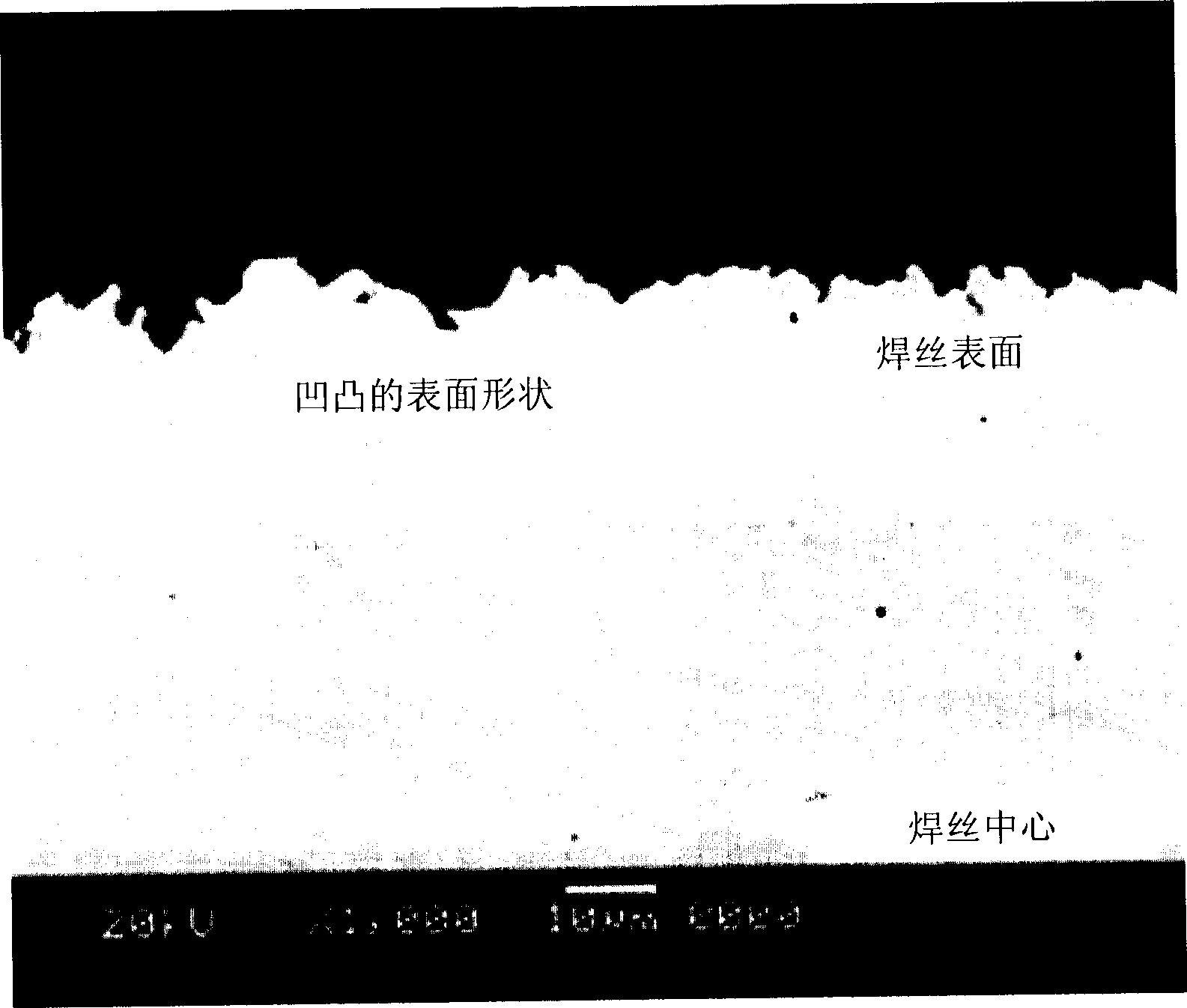
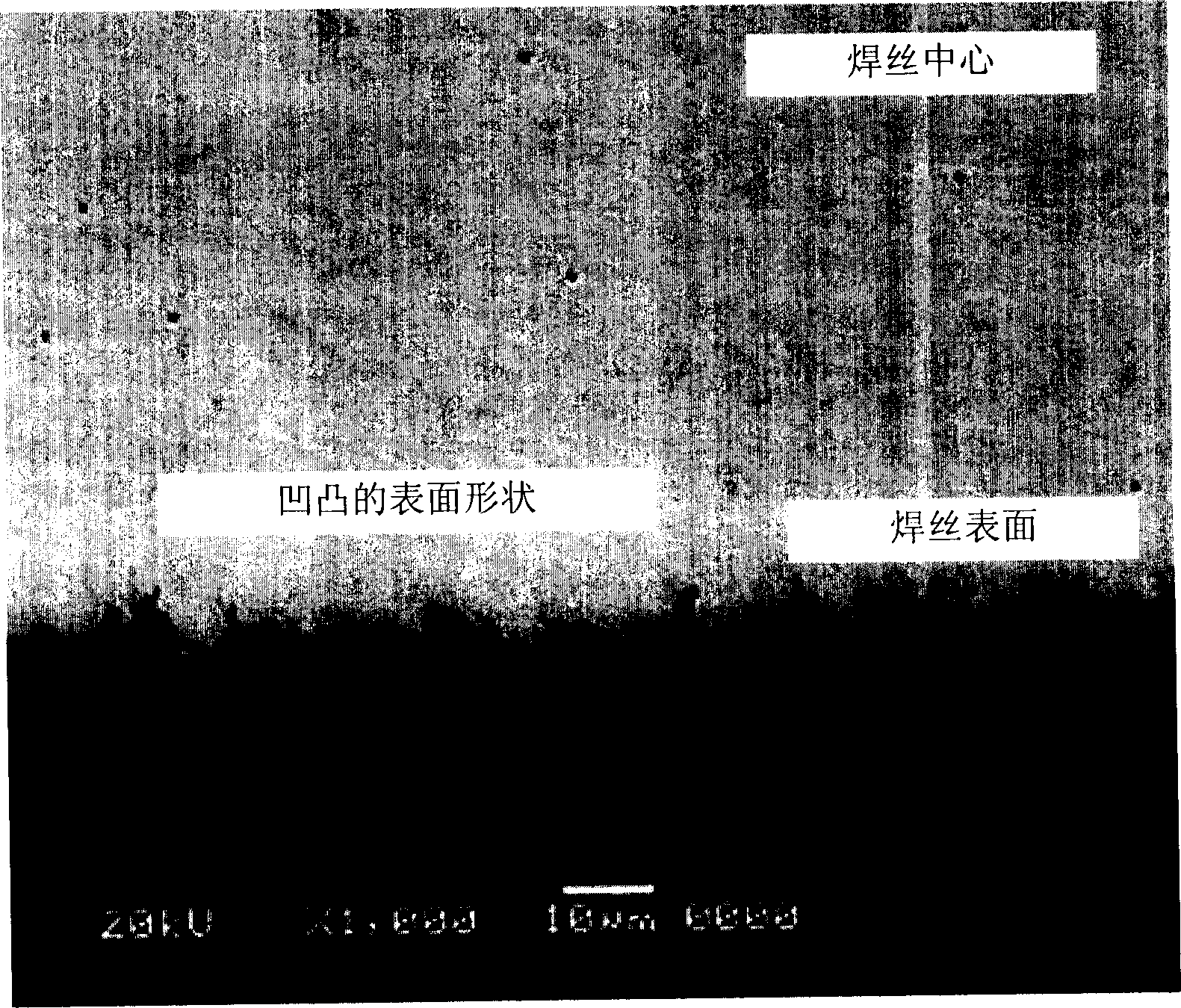
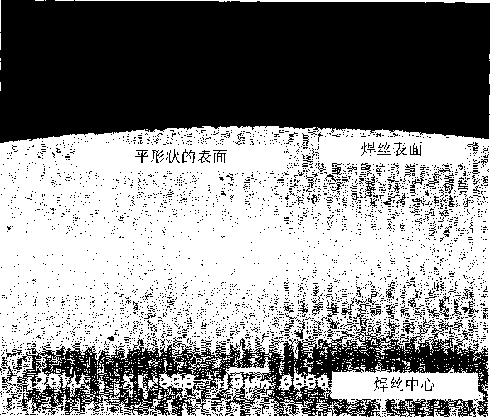

Image

  • Copper-free wires for gas-shielded arc welding
  • Copper-free wires for gas-shielded arc welding
  • Copper-free wires for gas-shielded arc welding

Examples


Embodiment Construction

[0019] Preferred embodiments are described in detail below with reference to the accompanying drawings.

[0020] As mentioned above, although the surface of copper-free welding wire needs to have special properties in order for the welding wire to stably contact the contact tip, conventional techniques have proposed methods to make the welding wire form the following properties, and these methods are limited to the surface roughness of the welding wire surface , specific surface area, etc. are controlled within a predetermined range, but these methods cannot guarantee stable contact between the contact tip and the welding wire.

[0021] The present inventors conducted various experiments in order to impart special properties to the surface of the welding wire to replace the copper-plated layer on the surface of the welding wire. As a result, the present inventors found that the wire surface can be divided into three categories, namely, the plane formed only by the machined sur...


PUM

PropertyMeasurementUnit
surface roughnessaaaaaaaaaa

Abstract

The invention relates to a copper-free welding wire for gas shielded arc welding. The copper-free wire for gas shielded arc welding includes a flat processed surface; and depressions formed circumferentially in a negative direction (toward the center of the wire) with respect to the processed surface reference. The ratio (dr / di) of the actual length (dr) of the arc to the apparent length (di) of the arc is within the range of 1.015-1.515. The lubricant residue on the wire surface is equal to or less than 0.50g / W.kg. The coating agent of the welding wire on the surface of the welding wire is 0.03-0.70g / W.kg. The coating agent includes at least one selected from the group consisting of liquid animal oil, vegetable oil, mineral oil, mixed oil and synthetic oil. The wire is in constant contact with the contact tip during welding, thus providing good arc stability and wire feedability while reducing the amount of spatter.

Description

technical field [0001] The present invention generally relates to a non-copper-coated welding wire for gas-shielded arc welding, and more specifically, to a non-copper-coated welding wire for gas-shielded arc welding, which can ensure arc stability during semi-automatic welding or automatic welding, thereby reducing the amount of spatter and enhanced wire feedability. Background technique [0002] Recently, with the development of automatic welding, the application of gas-shielded arc welding wires has rapidly increased, and as a result, gas-shielded arc welding wires are widely used especially in the fields of automobile industry, shipbuilding industry, construction industry and the like. In this way, welding wire is widely used in the above-mentioned different fields, and in order to ensure the properties of the welding wire, such as electrical conductivity, wire feedability, corrosion resistance, etc., the surface of the welding wire is generally copper-plated. In the ca...

Claims


Application Information

Patent Timeline
Patent Type & Authority Applications(China)
IPC IPC(8): B23K35/02B23K9/16B23K35/36
CPCB23K35/0261B23K35/36B23K35/40B23K9/16
Inventor 金容哲方焕喆
Owner KISWEL LTD
Learn More