Method for machining deep hole and its special tool

A processing method and a technology for processing cutting tools, which are applied in the field of mechanical processing, can solve the problems of not being able to meet the structural requirements of hollow shafts, processing rigidity, and unsatisfactory effects, and achieve the effects of improving efficiency, simplifying the repair process, and meeting technical requirements

Inactive Publication Date: 2006-06-07
SHENYANG LIMING AERO-ENGINE GROUP CORPORATION
View PDF0 Cites 34 Cited by
  • Summary
  • Abstract
  • Description
  • Claims
  • Application Information

AI Technical Summary

Problems solved by technology

If we carry out deep hole boring, the effect is still unsatisfactory due to the limitation of the hollow shaft structure
However, the o

Method used


Image

  • Method for machining deep hole and its special tool
  • Method for machining deep hole and its special tool
  • Method for machining deep hole and its special tool

Examples


Example Embodiment

[0055] Example 1 Application 1 of deep hole boring processing test of cemented carbide long shank

[0056] Test application conditions:

[0057] 1. The processing equipment is KDM-18 deep hole boring machine;
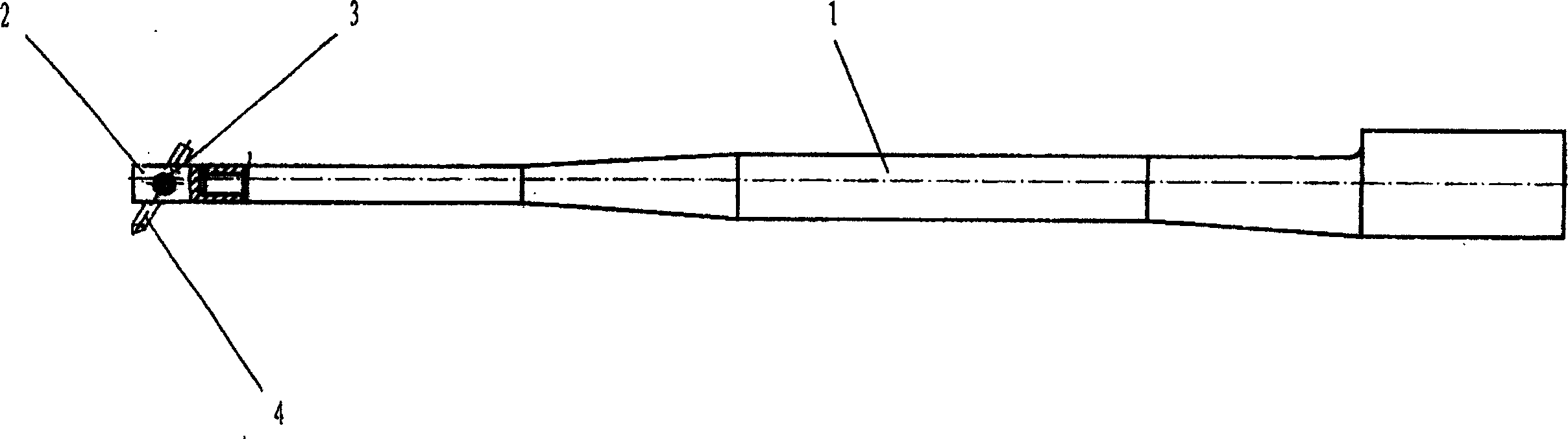
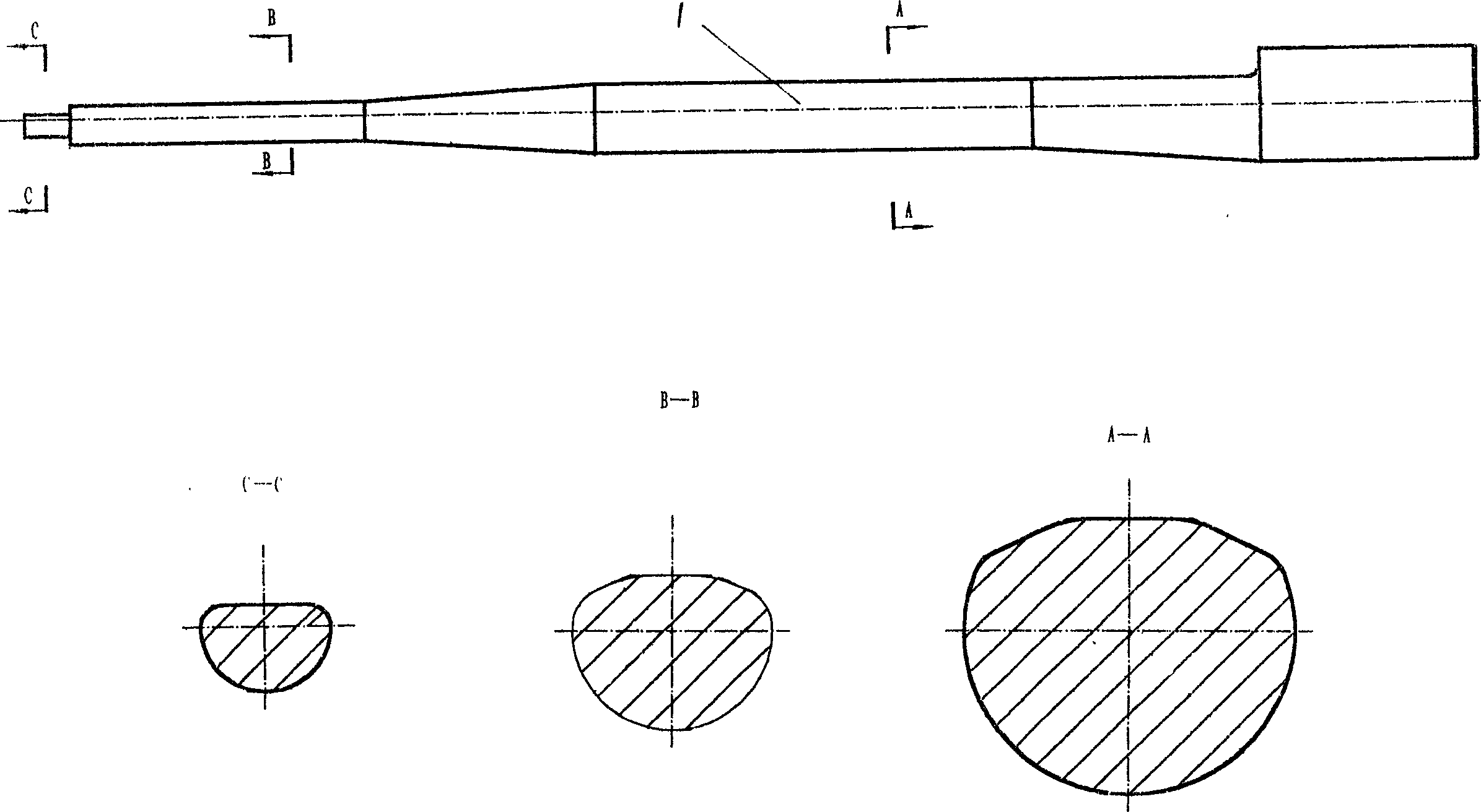
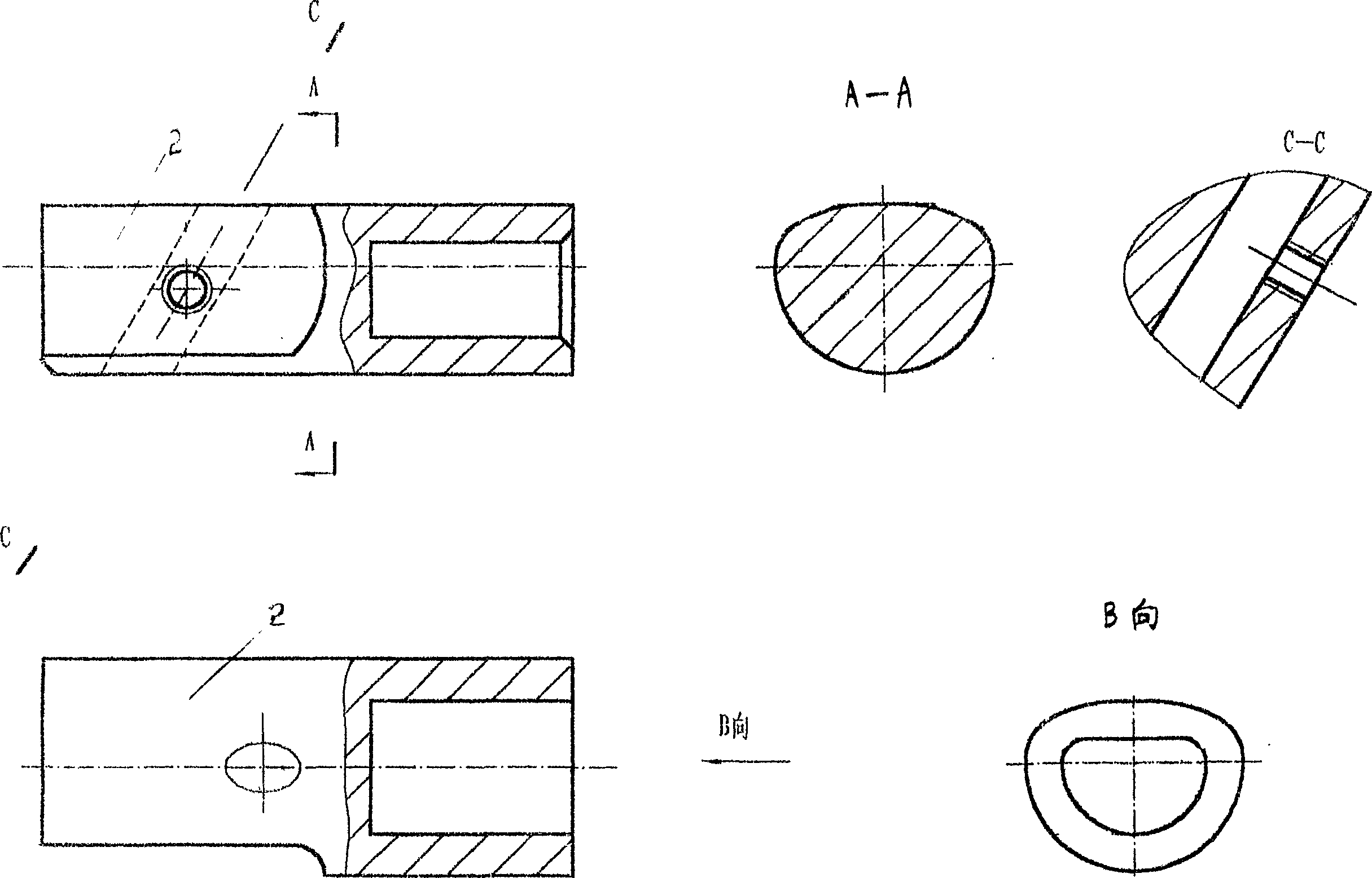
[0058] 2. The tooling used is: cemented carbide long shank, structural steel processing tool material is YT15 turning tool, and the template for copying (if attached) Picture 9 Shown) and so on.

[0059] In this simulation test, we can find that after the knife is loaded, the tool yield of the long carbide shank, the rebound of the shank during the machining process, and the tremor near the root are all significantly better than the traditional structure. Steel arbor. The data collected during the application process is shown in Appendix 1.

Example Embodiment

[0060] Example 2 Deep hole machining application of a certain hollow shaft (see attached Figure 8 )

[0061] Application conditions:

[0062] 1. The equipment is DDM-18 deep hole boring machine;

[0063] 2. Tooling used: long carbide shank, tool material YG8 turning tool, template for copying (if attached Picture 9 Shown).

[0064] In this embodiment, we use a cemented carbide tool holder to attach the attachment according to the above-mentioned process. Figure 8 The hollow shaft shown is subjected to deep hole machining, and the machining result is similar to the hollow shaft in Example 1. Attached table 2 shows the processing attachment Figure 8 The hollow shaft shown is the application parameters and machining results. Among them: the cutting test parameters are consistent with the parameters of No. 2, 3, 4, 5, and 6 in Appendix 1, and the effect is very realistic.

[0065] Application conclusion: Adopt the cemented carbide tool holder to attach Figure 8 The hollow shaft sh...

Example Embodiment

[0066] Example 3 Deep hole machining application of a certain hollow shaft (see attached Figure 8 )

[0067] Application conditions:

[0068] 1. The equipment is DDM-18 deep hole boring machine;

[0069] 2. Tooling used: carbide tool holder, turning tool with YT15 tool material, and template for copying (if attached Picture 9 Shown).

[0070] In this test project, we used a cemented carbide long shank to attach Figure 8 The hollow shaft shown is processed for deep hole machining, and the machining results are similar to the first type of hollow test shaft. The cutting test parameters are consistent with the parameters of No. 2, 3, 4, 5, and 6 in the attached table, and the effect is very satisfactory.

[0071] Schedule 1

[0072] Serial number

[0073] Preface


PUM


Abstract

The deep hole machining process includes the following successive steps: drilling hole, expanding, coarse reaming, boring and finish reaming. The wall thickness difference in the whole machined length is controlled in 0.02-0.10. The cutter for deep holes machining is long cutter bar of hard alloy and in the length/diameter ratio of 10-20. The deep hole machining technology of the present invention is advanced.

Description

Technical field: [0001] The invention relates to mechanical processing technology, and in particular provides a deep hole processing method and a special cutter. Background technique: [0002] In mechanical engineering technology, deep hole processing has always been a major technical difficulty, and this type of technology has always attracted attention. In deep hole machining, it is sometimes required to achieve high hole machining accuracy; for the machining of hollow shaft parts, one of the main processing difficulties is the control of the thickness difference value of the hollow shaft wall. [0003] The traditional deep hole processing and forming processes are: drilling, reaming, rough reaming with large cone face, rough reaming with small cone face, fine reaming with large cone face, fine reaming with small cone face, boring small head and tail holes. Processing deep holes is often carried out on deep hole drilling machines (see attached Figure 7 ), the drill pipe ...

Claims


Application Information

Patent Timeline
IPC IPC(8): B23P13/00B23B29/02B23B41/02B23K1/008C09J5/02C09J5/06F16B11/00
Inventor 姜雪梅刘伟龙哈剑义
Owner SHENYANG LIMING AERO-ENGINE GROUP CORPORATION
Why Eureka
Try Eureka