Disk coating system

A technology for processing systems and disks, applied in coatings, metal material coating processes, instruments, etc., can solve problems such as extending the floor space

Inactive Publication Date: 2006-07-05
INTEVAC
View PDF7 Cites 14 Cited by
  • Summary
  • Abstract
  • Description
  • Claims
  • Application Information

AI Technical Summary

Problems solved by technology

If there are any additional systems, the footprint is extended and the number of final stations is governed by equipment space constraints

Method used


Image

  • Disk coating system
  • Disk coating system
  • Disk coating system

Examples


Embodiment Construction

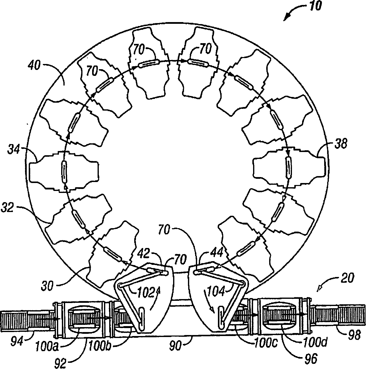
[0022] Figure 1 shows a prior art substrate processing system in which like elements have been given like reference numerals. As shown in FIG. 1 , the system includes a processing unit 10 and a substrate processing system 20 . The processing unit 10 includes a plurality of processing stations 30 , 32 , 34 etc. installed on a main vacuum chamber 40 . The processing stations 30 , 32 , 34 etc. are arranged in a circular arrangement with respect to the circular central main vacuum chamber 40 . The processing unit 10 also includes a loading station 42 for loading the system with substrates for processing and an unloading station 44 for unloading the substrates from the system after processing. The substrate is generally a substrate used in the manufacture of magnetic hard disks or used in the manufacture of magneto-optical discs. The substrate and the final disk contain a central opening. The substrate processing system may also include a vacuum pump, power supply and controller...


PUM


Abstract

There is described a disk processing and manufacturing equipment in which the processing chambers are stacked on top of each other and in which the disks move through the system on disk carriers which are adjustable to take disks of varying sizes. The disks enter the system through a load zone and are then installed into disk carriers. They move in the carriers sequentially through processing chambers at one level and then move to the other level in a lift or elevator. At this other level, the disks again move sequentially through the system on that level and then exit at an unload zone.

Description

technical field [0001] The present invention relates to systems and methods for processing and handling thin substrates, such as those used in the manufacture of magnetic disks. More specifically, the present invention relates to an improved system for processing substrates simultaneously at several processing stations and using various coating techniques, including on both sides. Background technique [0002] As stated by disk manufacturers in the N.Y. Times July 1, 2002 "The plastic platters they sell you to take home are higher gross profit products than modern computer hard drives". However, we believe that disks today contain as much technology as complex computer chips. The purpose of the present invention is to improve the manufacture of such discs to allow higher technical innovations regarding the discs to help reduce costs. [0003] US Patents 5,215,420 and 5,425,611 describe equipment that is primarily used today to manufacture disks. Such a device is available...

Claims


Application Information

Patent Timeline
Patent Type & Authority Applications(China)
IPC IPC(8): C23C14/00C23C16/00C25B11/00C25B13/00C25B9/00C23F1/00H01L21/306B65H1/00C23C14/56C23C16/458C23C16/54G11B5/84H01L21/00
CPCC23C16/4587C23C14/568C23C16/54G11B5/00G11B5/8404H01L21/67161H01L21/67178H01L21/6719H01L21/67196H01L21/67207H01L21/67236H01L21/67276
Inventor 凯文·P.·费尔拜恩特里·布卢克克雷格·马里恩罗伯特·E.·韦斯
Owner INTEVAC
Why Eureka
Try Eureka