Flame-proof moving bed calcination device

A calcination device and moving bed technology, applied in forging furnaces, furnaces, furnace types, etc., can solve the problems of material heat transfer, poor mass transfer, low production capacity of a single device, and slow heating of materials to achieve high thermal efficiency and calcination reaction The effect of uniform time and avoiding overburning of materials

Inactive Publication Date: 2006-07-12
INST OF PROCESS ENG CHINESE ACAD OF SCI
View PDF0 Cites 6 Cited by
  • Summary
  • Abstract
  • Description
  • Claims
  • Application Information

AI Technical Summary

Problems solved by technology

For the calcination of powder materials, the heat transfer and mass transfer of materials in rotary kilns, multi-layer furnaces, and tunnel kiln

Method used


Image

  • Flame-proof moving bed calcination device

Examples


Embodiment Construction

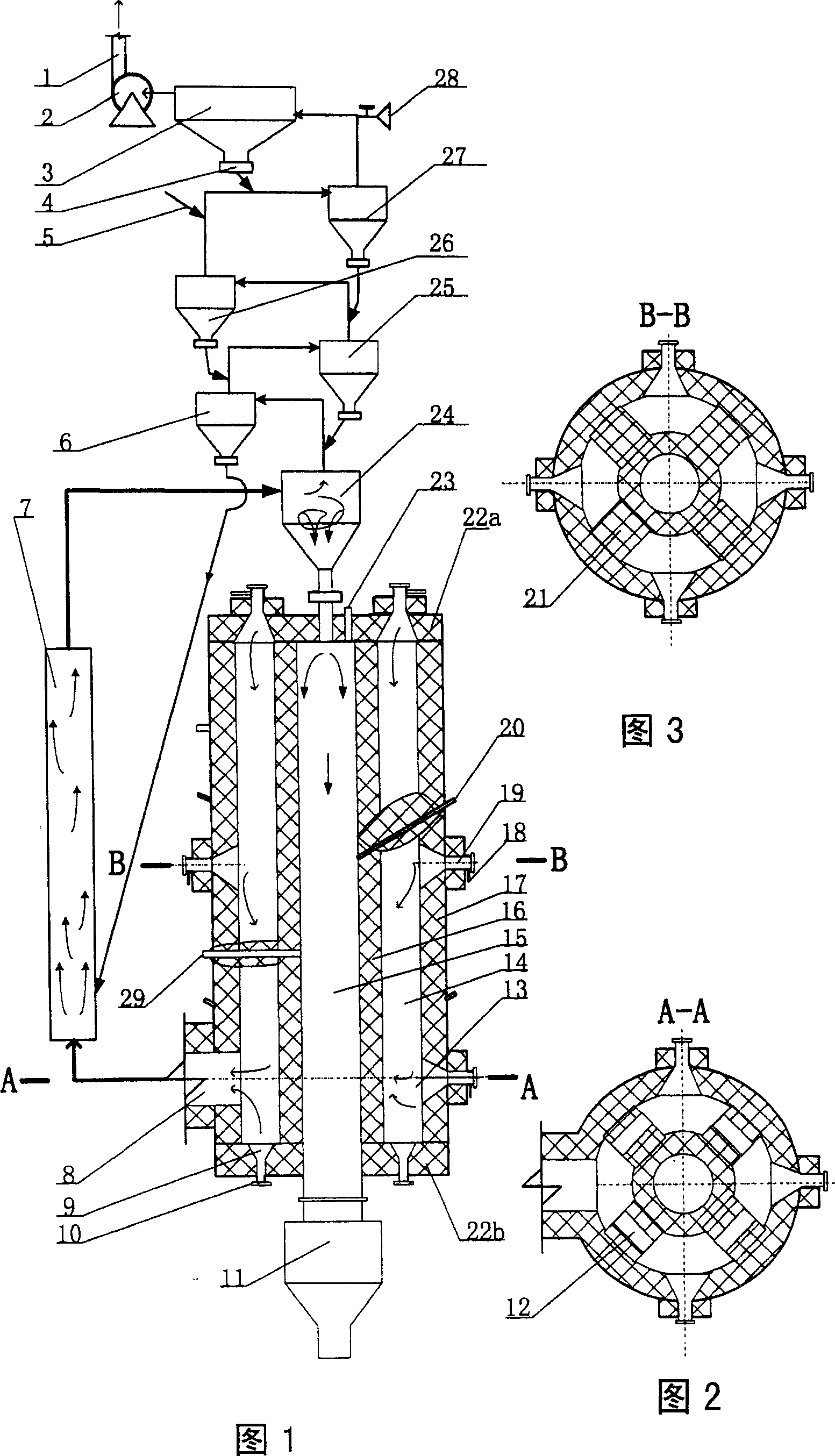
[0031] The structure of the flame-chambered moving bed calcination device of the present invention is shown in FIG. 1 . The flame moving bed calciner is composed of three parts: the preheating part, the fast fluidized bed heater and the flame moving bed calciner. The preheating part includes chimney 1, fan 2, bag filter 3, air lock valve 4, feed inlet 5, four-stage cyclone preheater 6, high-temperature gas-solid separator 24, three-stage cyclone preheater 25, two The first-stage cyclone preheater 26, the first-stage cyclone preheater 27 and the cold air valve 28; wherein, the high-temperature gas-solid separator 24 is provided with a four-stage cyclone preheater 6 and a third-stage cyclone preheater 25 in reverse order. , two-stage cyclone preheater 26 and one-stage cyclone preheater 27, four-stage cyclone preheater 6 is located at the top left of high-temperature gas-solid separator 24, and its right side is connected to the high-temperature flue gas pipeline at the top of hi...


PUM

PropertyMeasurementUnit
Average particle sizeaaaaaaaaaa

Abstract

The invention relates to a muffle moving bed incineration device, which can solve the problems of local temperature overheating of incinerator which can cause overheating material, can strengthen the heating speed of incineration material, and can effectively utilize the discharged energy when burning fuel in the burning chamber. The invention utilizes the high-temperature flame and high-temperature smoke to indirectly heat the incinerator of moving bed; the high-temperature smoke can quickly enter high-velocity fluidized bed; the high-temperature gas can form gas-solid high-velocity fluidized mixing heating on the preheated material, therefore, the high-temperature gas and material can generate effective high-velocity heat and mass transfer; the material which has been heated to demanded temperature via the gas-solid separation of high-temperature gas-solid separator is fed into the incinerator of moving bed to be incinerated; the separated gas is used to preheat material; the hot material is fed into storehouse via the cooling discharge device; the average residence time of material in the incinerator of said muffle moving bed incinerator can be adjust between several minutes to hours, while the incinerator temperature is controlled between 500-1200Deg. C and the furnace temperature difference is controlled in í‚5Deg. C.

Description

technical field [0001] The invention relates to a flame-chambered moving bed calcination device, which relates to the technical field of calcination equipment. Background technique [0002] At present, the calcining equipment includes rotary kiln, multi-layer furnace, tunnel kiln and so on. For the calcination of powder materials, the heat transfer and mass transfer of the materials in the rotary kiln, multi-layer furnace, and tunnel kiln calciner are poor, and the material is heated slowly, resulting in high energy consumption and low production capacity of a single equipment. Contents of the invention [0003] The purpose of the present invention is to provide a flame-trap moving bed calcination device, which has the characteristics of rapid fluidization technology, such as fast heat transfer and mass transfer, uniform temperature in the furnace, and low energy consumption. It also has uniform calcination reaction time and can effectively avoid material burnt. [0004]...

Claims


Application Information

Patent Timeline
IPC IPC(8): B21J17/00
Inventor 卢旭晨
Owner INST OF PROCESS ENG CHINESE ACAD OF SCI
Why Eureka
Try Eureka