Screw pile forming device and forming method

A technology for threaded piles and pile formation, which is applied in drilling equipment and methods, sheet pile walls, earthwork drilling, etc., can solve the problems of many pile formation processes, easy collapse of hole walls, and inability to construct piles.

Inactive Publication Date: 2006-07-26
刘润郊
View PDF1 Cites 13 Cited by
  • Summary
  • Abstract
  • Description
  • Claims
  • Application Information

AI Technical Summary

Problems solved by technology

[0003] The purpose of the present invention is to provide a pile-forming device and a pile-forming method for threaded piles, to overcome the fact that the existing threaded piles have many pile-forming pro

Method used


Image

  • Screw pile forming device and forming method
  • Screw pile forming device and forming method
  • Screw pile forming device and forming method

Examples


specific Embodiment approach 1

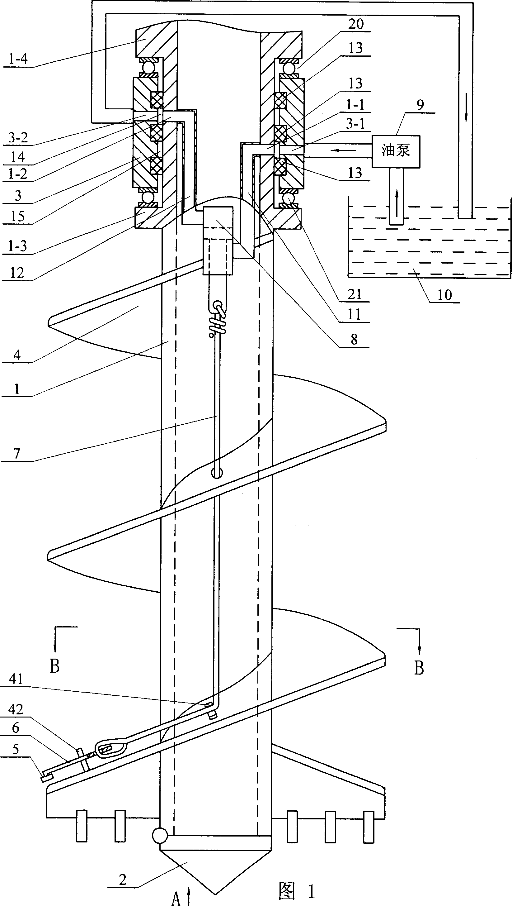
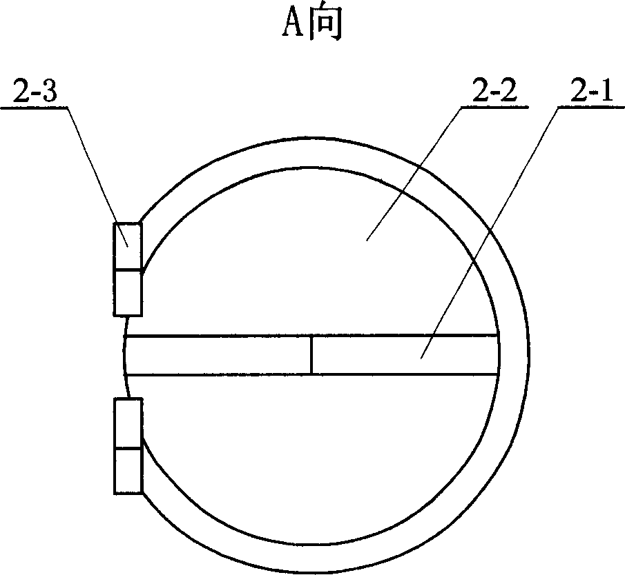
[0006] Specific embodiment one: below in conjunction with Fig. 1 and figure 2 , Figure 4 This embodiment will be described. This embodiment consists of a drill pipe 1, a drill bit 2, a jacket 3, a blade 4, a rolling wheel 5, a swing rod 6, a pulling rope 7, an oil cylinder 8, an oil pump 9, an oil tank 10, an oil inlet pipe 11, an oil return pipe 12, and a guide device 41 and three sealing rings 13, the blade 4 surrounds the outer surface of the hollow drill pipe 1, the drill bit 2 is hinged on the lower end of the drill pipe 1 and closes the lower end of the drill pipe 1, and the jacket 3 is set on the upper part of the drill pipe 1 and sleeved On the outer surface of the drill pipe 1, three sealing rings 13 are sequentially arranged between the inner surface of the outer casing 3 and the outer surface of the drill pipe 1 from top to bottom and form a first ring respectively between the two sealing rings 13. 14 and the second annulus 15, the oil outlet end of the oil pump ...

specific Embodiment approach 2

[0007] Specific Embodiment 2: The present embodiment will be specifically described below with reference to FIG. 1 . The difference between this embodiment and Embodiment 1 is: it also includes No. 1 bearing 20 and No. 2 bearing 21, the upper end of the outer cover 3 pushes against the lower end of the upper shoulder 1-4 of the drill pipe 1 through the No. 1 bearing 20, and the outer cover 3 The lower end of the drill rod 1 is pressed on the upper end of the lower shoulder 1-3 of the drill rod 1 by No. 2 bearing 21. In this way, the up and down displacement of the drill rod 1 will not cause the axial movement of the jacket 3 . Other components and connections are the same as those in Embodiment 1.

specific Embodiment approach 3

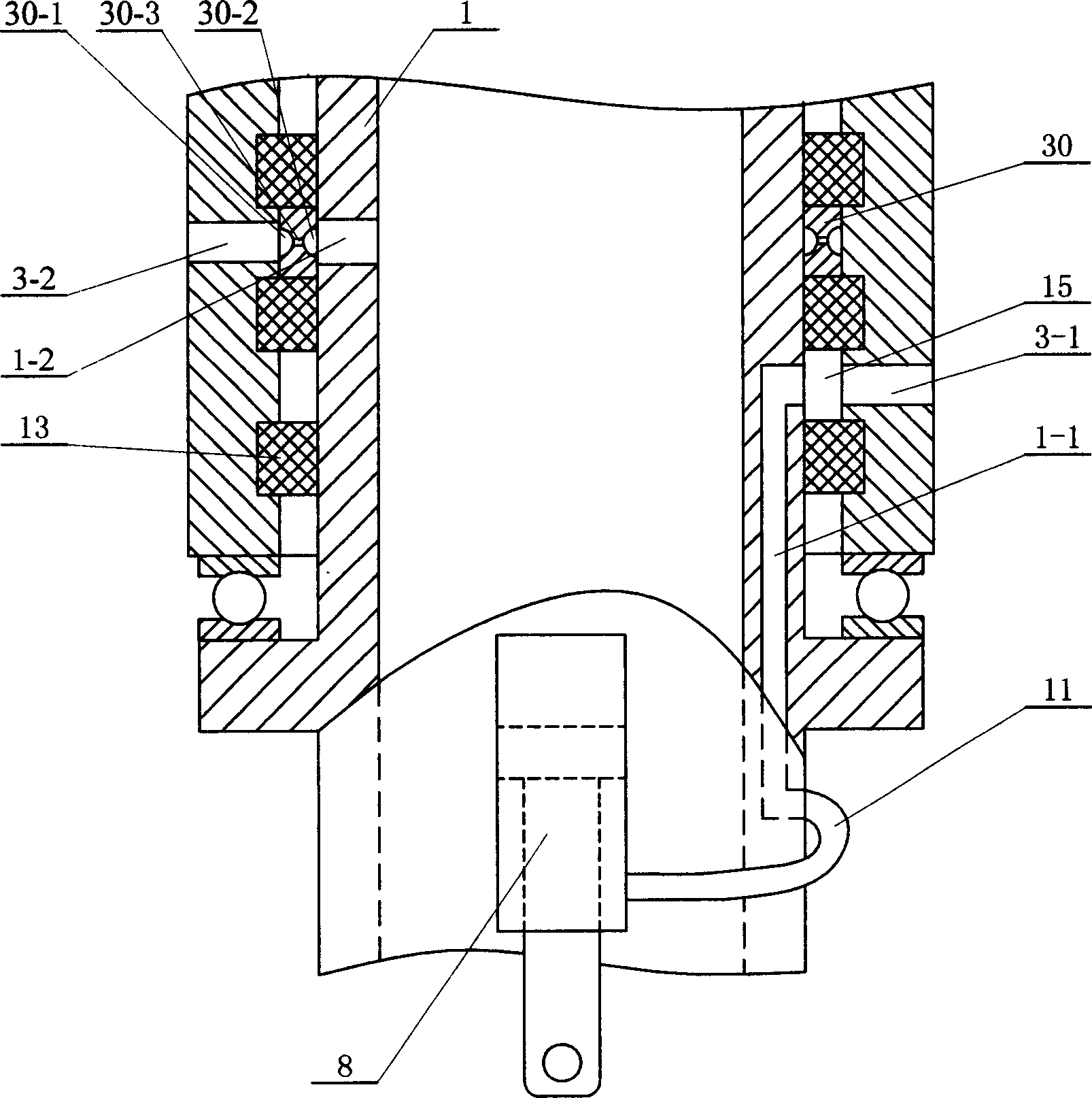
[0008] Specific embodiment three: below in conjunction with Fig. 1 and image 3 This embodiment will be specifically described. The difference between this embodiment and Embodiment 1 is: it also includes a flower cover 30, which is arranged in the first annular space 14, and an outer ring groove 30-1 is opened on the outer circular surface of the flower cover 30, and the flower cover 30 There is an inner ring groove 30-2 on the inner hole surface of 30, and the outer ring groove 30-1 and the inner ring groove 30-2 are connected through the hole 30-3, and the outer ring groove 30-1 is connected with the second through hole 3 -2 is connected, and the inner ring groove 30-2 is connected with the second through hole 1-2. Such setting enables the sealing ring 13 to be axially positioned to ensure the smooth flow of the oil passage. Similarly, a flower cover 30 can also be arranged in the second annular space 15 . Other components and connections are the same as those in Embodim...


PUM

PropertyMeasurementUnit
Depthaaaaaaaaaa

Abstract

The invention relates to a post-construction device of screw post and relative method, which uses pump to fill concrete to overcome the defects of present screw posts which need more processes and can not construct in worse geologic condition. It comprises a drill rod (1), a drill head (2), an outer sheath (3), a leaf (4), a rolling wheel (5), a swing rod (6), a drawn wire (7), an oil cylinder (8) and a hydraulic system. Wherein, one end of drawn wire (7) is fixed on the piston rod of oil cylinder (8) and another end is fixed on one end of swing rod (6); the another end of swing rod (6) is connected to the rolling wheel (5). The invention can complete the construction of screw post in one time, which comprises: first drilling a post hole; filling the concrete in the inner hole of drill rod (1) into the post hole; the hydraulic system retracts the piston rod of oil cylinder to rotate the swing rod counterclockwise; the edge of rolling wheel enters the inner wall of post hole; upwards lifting the drill rod and rotating the drill rod to roll out a groove and inserting the steel cage into the post concrete.

Description

technical field [0001] The invention relates to a pile-forming device using the method of pumping concrete to form piles, and also relates to a pile-forming method using the device. Background technique [0002] Authorized notice number CN2490208Y "pump concrete hole bottom shot grouting device" discloses a kind of drilling and pile forming device for pile foundation engineering. When using this device to form a pile, after drilling to the design elevation, use a pump to shoot grout to the bottom of the hole through the grout delivery pipe and the grout injection pipe, so as to increase the diameter of the bottom of the pile hole, so that the bottom diameter of the formed pile becomes larger, and the single pile Increased bearing capacity. Although this kind of pile has a high bearing capacity, the grout delivery and grout injection pipes are easily blocked during construction in winter. As the name suggests, "threaded pile" is a threaded thread that spirals around the out...

Claims


Application Information

Patent Timeline
IPC IPC(8): E02D5/56E21B7/00
Inventor 刘润郊
Owner 刘润郊
Why Eureka
Try Eureka