
New laser colour display device

A color display and laser technology, applied to lasers, laser components, semiconductor lasers, etc., can solve the problems of simple systems that have not been seen yet, and achieve the effects of clear photoelectric interface, high stability, and simple device structure

Inactive Publication Date: 2006-08-02
SHANDONG NORMAL UNIV
View PDF0 Cites 24 Cited by
  • Summary
  • Abstract
  • Description
  • Claims
  • Application Information

AI Technical Summary

Problems solved by technology

Relevant institutions in China have also done a lot of research on the use of lasers for display, but so far no solutions and related reports that are simple and suitable for large-scale applications have been seen.

Method used


Image

  • New laser colour display device
  • New laser colour display device

Examples


Embodiment

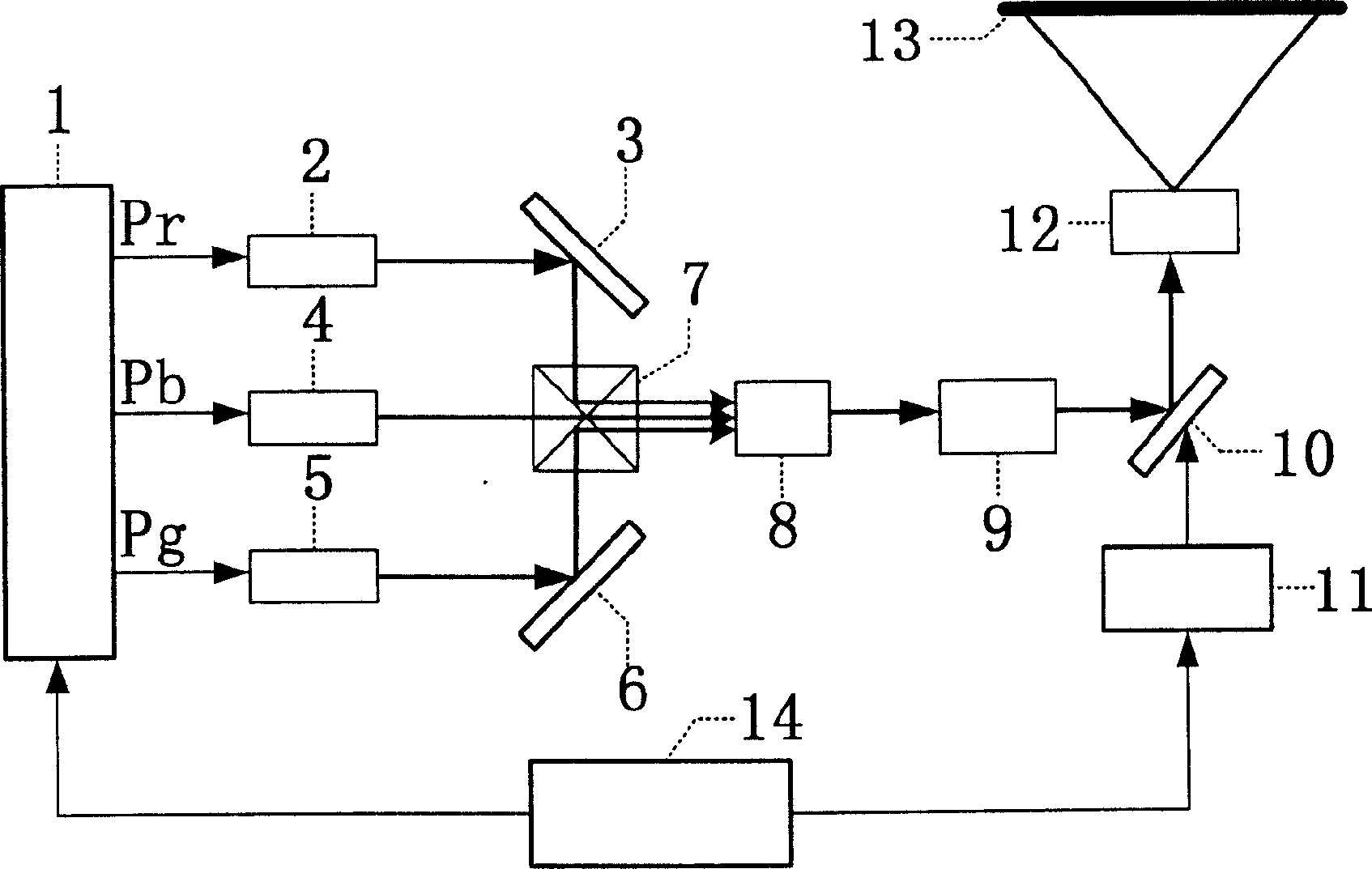
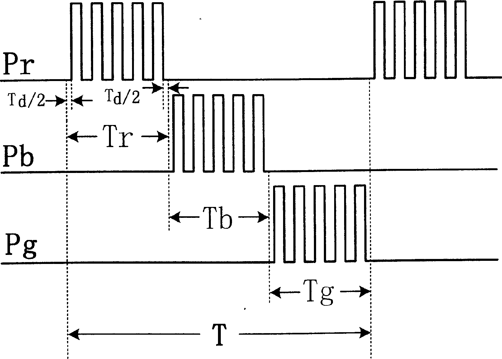
[0022] figure 1 Among them, the timing control module 1 is a pulse width modulation signal PWM generator, which is connected with the red laser 2, the blue laser 4 and the green laser 5 in the pulsed laser emission module. It sends out three channels of PWM pulses Pr, Pb, Pg corresponding to each laser, and the duty cycle of the three channels of PWM signals can be adjusted respectively to adjust the output light intensity of red, blue and green lasers to ensure A balanced color reproduction is obtained; Tr, Tb, and Tg are the light-emitting time slots of the three-way lasers, and T is a cyclic light-emitting period. The setting of T, the division of time slots and the duty cycle of PWM are determined by the fluorescence lifetime of the laser crystal used in the three lasers, the proportional relationship between the output light intensities of the lasers, and the system loss, that is, the output light intensities of the three lasers The larger difference can be controlled by...


PUM


Abstract

The present invention discloses a new-type laser color display device. It has time sequence controller module, red light laser, green light laser, blue light laser, decoherer, liquid crystal light valve, light valve drive circuit and lens system. Besides, said device also includes the components, of light modulator, reflector, beam-combining prism, beam-expanding prism and display screen. Said invention also provides the connection mode of all the above-mentioned components, and the working principle of said laser color display device.

Description

technical field [0001] The invention relates to a display device, in particular to a novel laser color display device which utilizes red, green and blue primary color lasers to be modulated and output through the same optical path in time division, and finally forms a color display. Background technique [0002] Televisions and computer monitors include liquid crystal, plasma, and CRT monitors. Due to the limitation of their imaging mechanism, there is a problem that the color rendering area of ​​the image is not enough, and the original color cannot be as close as possible to the greatest extent. [0003] The color laser display device is a new type of large-screen full-color display technology developed in recent years. Due to the latest development of red, green, and blue lasers, the area of ​​the chromaticity triangle formed by the displayed color is larger than that formed by phosphor or other light sources, so the displayed color is more vivid, more real, and has a hig...

Claims


Application Information

Patent Timeline
IPC IPC(8): G02F1/35G02F1/01G09G3/00H01S5/00G02B27/18
Inventor 杨济民刘杰符秋丽
Owner SHANDONG NORMAL UNIV
Learn More