
Permanent-magnet eddy current retarder for vehicle

A permanent magnet eddy current and retarder technology, which is applied in the direction of permanent magnet clutches/brakes, etc., can solve the problems of complex structure of hydraulic retarder, high heat generation of electromagnetic coil, long action response time, etc., and achieve light weight, Low energy consumption and good magnetic sealing effect

Inactive Publication Date: 2006-08-02
BEIJING UNIV OF TECH
View PDF0 Cites 10 Cited by
  • Summary
  • Abstract
  • Description
  • Claims
  • Application Information

AI Technical Summary

Problems solved by technology

The structure of the hydraulic retarder is complex, the low-speed braking effect is poor, and the action response time is long; the eddy current retarder is equipped with a large number of electromagnetic coils and magnetic cores, so it has a large mass and consumes a large amount of current during braking. The coil has high heat generation and high energy consumption. The temperature rise of the main engine during operation causes the braking torque to attenuate seriously with the temperature rise.

Method used


Image

  • Permanent-magnet eddy current retarder for vehicle
  • Permanent-magnet eddy current retarder for vehicle
  • Permanent-magnet eddy current retarder for vehicle

Examples


Embodiment Construction

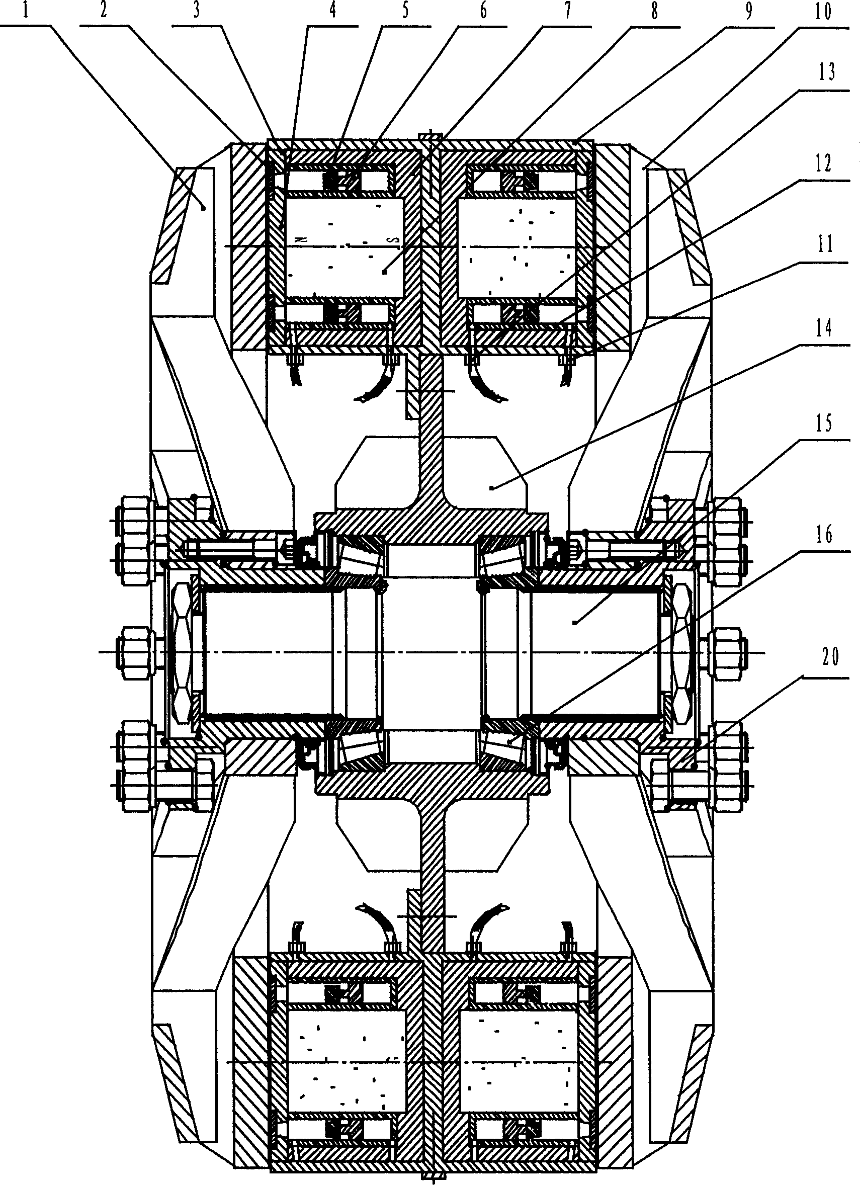
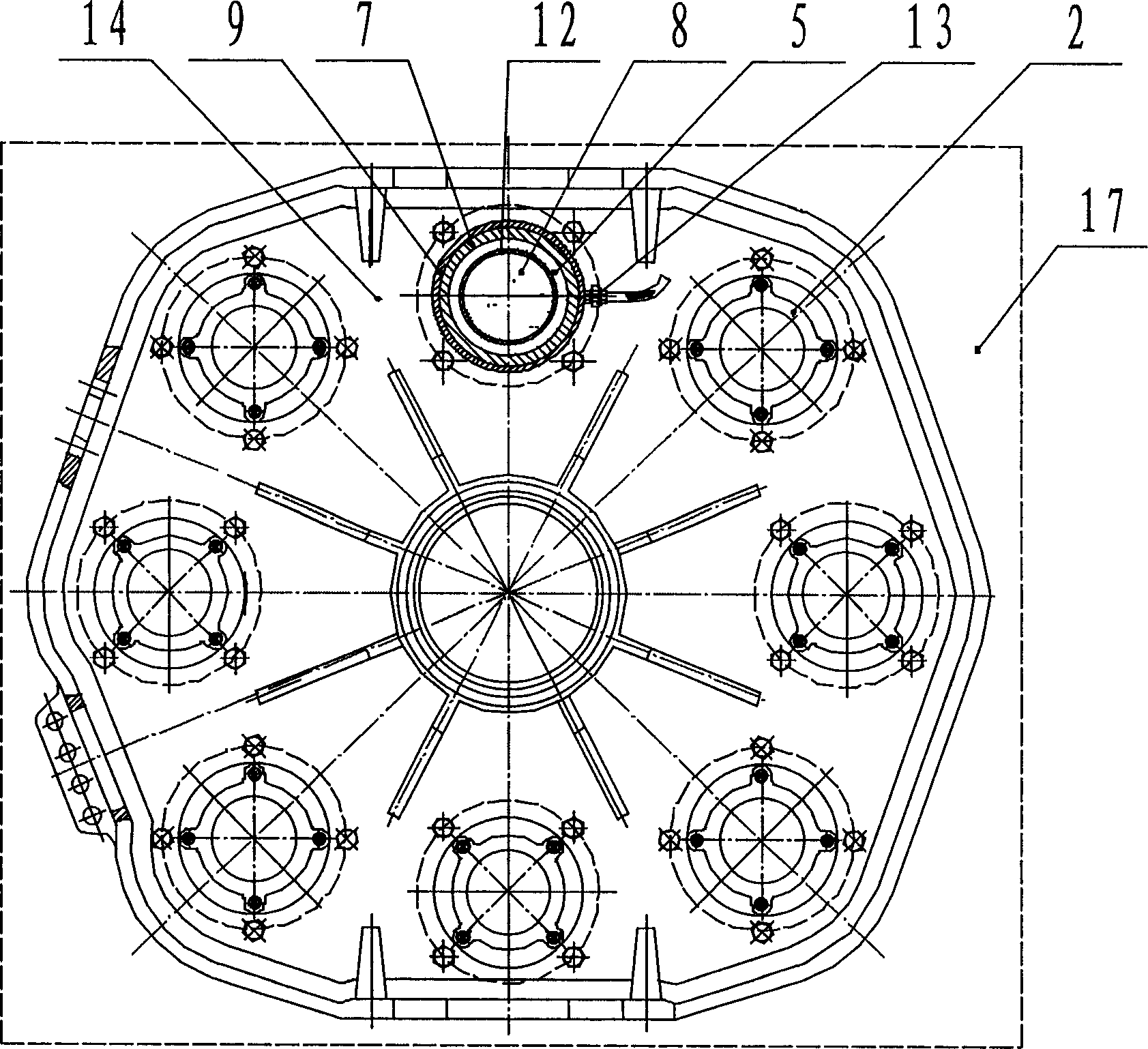
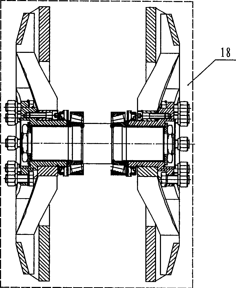
[0021] Embodiments of the present invention are as follows, see Figure 1~5 . The permanent magnet eddy current retarder for vehicles is composed of a stator assembly 17 and a rotor assembly 18. The stator assembly 17 is composed of a stator support 14 and 8 sets of magnetic switch assemblies 19 fixed on the stator support 14 along the circumferential direction. 1 and the large end faces of the right rotor disk 10 are parallel to the end faces of the magnetic switch assembly 19 and have an air gap. The magnetic switch assembly 19 is mainly composed of a NdFeB permanent magnet 8, a magnetic cylinder 7, a movable magnetic ring 5, a magnetic plate 4, and a magnetic ring 3, and is fixed with the pressure plate 2 to form a closed cavity, and the left air valve 11 and the right air valve 13 are respectively located on the left and right sides of the piston ring 6; the bottom of the inner side of the open magnetic cylinder 7 is provided with a step counterbore matching the size of th...


PUM


Abstract

A kind of permanent-magnet eddy current retarder for vehicles relates to the improvement of a kind of vehicle assistant brake equipment. It concludes left rotor dish, right rotor dish, splined shaft, stator support and magnistor components. The magnistor component conclude neodymium iron boron permanent-magnet, magnetic permeable jar, cylinder, magnetic permeable ring, magnetic permeable plank, kineto-magnetic permeable ring and piston ring; the stator support is positioned between the left rotor dish and right rotor dish and is homocentric mounted with them. The magnistor components are arranged in the stator support along circumference. The neodymium iron boron permanent-magnet is in the interior center of magnetic permeable jar. The cylinder is arranged between magnetic permeable jar and neodymium iron boron permanent-magnet. The magnetic permeable plank is arranged at outer side end face of the neodymium iron boron permanent-magnet. The magnetic permeable ring is arranged at the end face of the magnetic permeable jar. The piston ring pushes kineto-magnetic permeable ring to move in the cylinder.

Description

technical field [0001] The invention is an auxiliary braking device for decelerating automobiles through the reverse eddy current braking force generated in a rotating and non-contact rotor disk by using NdFeB permanent magnets as a braking force source, and relates to an auxiliary braking system for automobiles. Improvement of the moving device. Background technique [0002] With the rapid development of expressways and the improvement of road quality, the proportion of automobiles in transportation is constantly increasing. Future expressway traffic will be dominated by heavy-duty special vehicles and high-speed passenger vehicles. This requires the automobile industry to produce more vehicles suitable for highway and urban operation, these vehicles must not only have the characteristics of high power and high comfort, but also especially have extremely high safety. Therefore, the auxiliary braking system came into being to consume part of the driving kinetic energy befo...

Claims


Application Information

Patent Timeline
IPC IPC(8): H02K49/10
Inventor 李德胜李翔
Owner BEIJING UNIV OF TECH
Features
  • Generate Ideas
  • Intellectual Property
  • Life Sciences
  • Materials
  • Tech Scout
  • Unparalleled Data Quality
  • Higher Quality Content
  • 60% Fewer Hallucinations
Learn More