Atmospheric radio-frequency discharging high-speed cold plasma array generator

A technology of cold plasma and radio frequency discharge, which is applied in plasma, discharge tube, semiconductor/solid-state device manufacturing, etc., can solve the problems of short discharge area, small beam diameter, and uneven spatial distribution of cold plasma jet, and achieve Improve speed, improve work efficiency, and increase the effect of effective space range

Inactive Publication Date: 2006-08-02
TSINGHUA UNIV
View PDF0 Cites 27 Cited by
  • Summary
  • Abstract
  • Description
  • Claims
  • Application Information

AI Technical Summary

Problems solved by technology

[0003] When the technology adopts a coaxial structure design, the discharge area of ​​the gas along the flow direction is relatively long, and the cold plasma beam is relatively concentrated, but the beam diameter is relatively small (generally less than 10mm); if the flat structure design is adopted and the flow direction Vertical to the plate surface, although multiple beams of cold plasma jets can be generated, so that the overall diameter of the cold plasma jets becomes larger, but the discharge area along the gas flow direction is relatively short (the distance between the plates is generally 0.1-3mm), and the formed The cold plasma jet is not uniform enough in space

Method used


Image

  • Atmospheric radio-frequency discharging high-speed cold plasma array generator
  • Atmospheric radio-frequency discharging high-speed cold plasma array generator
  • Atmospheric radio-frequency discharging high-speed cold plasma array generator

Examples


Embodiment Construction

[0061] Figure 1-13 Several typical designs of the coaxial atmospheric pressure RF discharge cold plasma array generator are given.

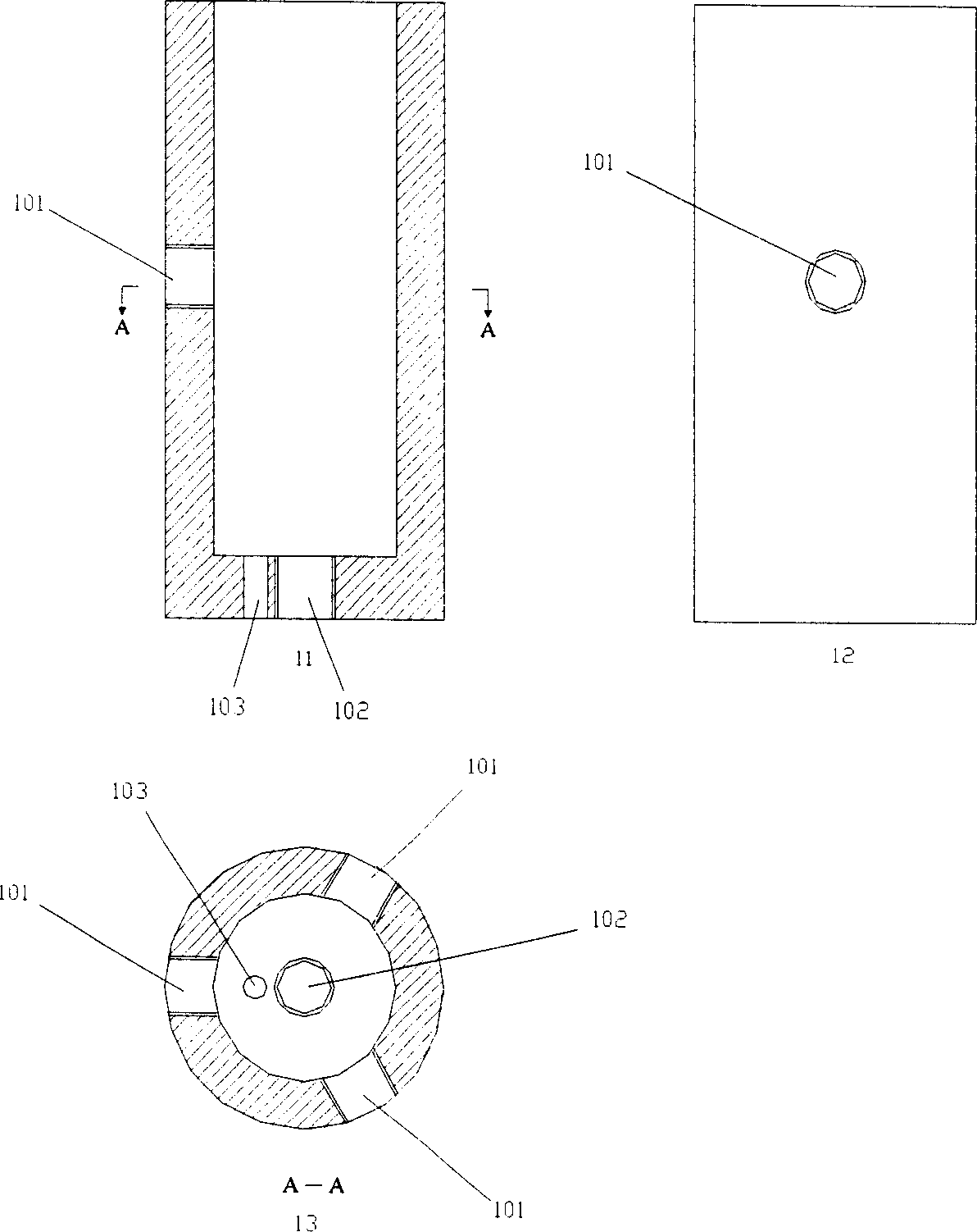
[0062] figure 1 It is a schematic diagram of the shell structure, in which the three drawings labeled 11, 12, and 13 represent the schematic diagrams of the front, the left side, and the top view, respectively. 101 represents the inlet of the cold plasma working gas, 102 represents the inlet of the cooling gas, and 103 represents the connection of the radio frequency power supply.

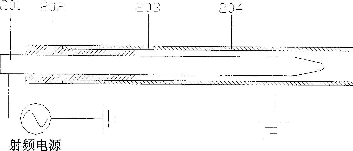
[0063] figure 2 It is a schematic diagram of the structure of a single coaxial atmospheric pressure radio frequency discharge cold plasma generator with a lateral air intake method and a cylindrical shape. 201 represents the internal electrode connected to the radio frequency power supply, 202 represents the insulating support, 203 represents the cold plasma working gas inlet, and 204 represents the external electrode.

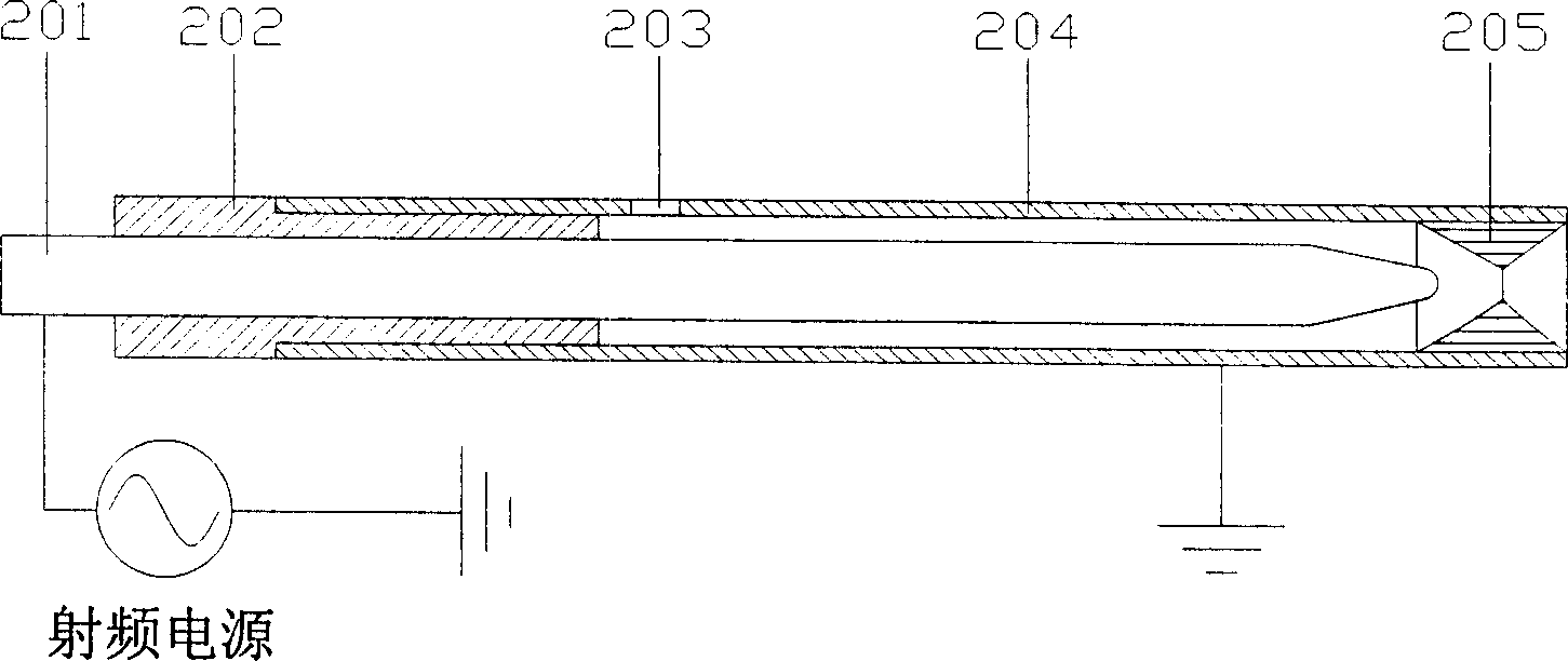
[0064] image 3 Schematic diagram of the...


PUM


Abstract

A high velocity cold plasma array generator of atmosphere radio frequency discharge consists of cylindrical shell and generator array formed by multiple single coaxial type of cold plasma generator .It featured as building generator array in cylindrical shell, setting a switching in hole of radio frequency power supply and inlet of cold plasma operation air on said shell, connecting internal electrodes of said generator to radio frequency power supply after they are parallel-connected and external electrodes to earthing after they are parallel-connected ,setting side director or axial direction operation air inlet on said generator and setting a cooling media inlet and outlet on said shell .

Description

technical field [0001] The invention belongs to atmospheric pressure cooling plasma generators, in particular to the field of array type atmospheric pressure cooling plasma generators. Background technique [0002] Although a large area of ​​non-equilibrium cold plasma can be produced under low pressure conditions, the existence of a vacuum chamber on the one hand greatly increases the manufacturing and maintenance costs of the equipment, on the other hand it also limits the geometric size of the workpiece to be processed, thus This greatly limits its scope of application. At present, there are two types of plasma that can be generated under atmospheric pressure conditions. One is thermal plasma, which is characterized by high gas temperature, about 10,000K, and is mainly used for plasma spraying, cutting, welding, waste treatment, Material surface processing and other fields. Due to the high temperature of hot plasma, it cannot be used for processing materials that are af...

Claims


Application Information

Patent Timeline
Patent Type & Authority Applications(China)
IPC IPC(8): H05H1/40H05H1/50H01J37/32H01L21/00
Inventor 李和平包成玉王华博孙文廷
Owner TSINGHUA UNIV
Why Eureka
Try Eureka