
Impact flow reactor for liquid-phase reaction

A technology of impinging flow reactor and liquid phase reaction, which is applied in chemical methods, chemical instruments and methods, chemical/physical processes, etc. to make liquids react with liquids. The shaft seal structure is easy to be damaged, etc., to achieve the effect of high efficiency mixing reaction uniformity, simplified structural design, and low failure rate

Active Publication Date: 2006-08-09
CHINA PETROLEUM & CHEM CORP +1
View PDF1 Cites 33 Cited by
  • Summary
  • Abstract
  • Description
  • Claims
  • Application Information

AI Technical Summary

Problems solved by technology

First of all, since the motor shaft on which the propeller is installed is a cantilever structure, if the shaft is long or the speed is fast, it is easy to cause vibration of the propeller and the motor shaft
Secondly, the motor shaft where the propeller is installed needs to be installed with a shaft seal structure on the reactor wall, which increases the manufacturing cost of the reactor, and the shaft seal structure is easily damaged during long-term operation, which affects the long-term operation of the reactor
Finally, this structure sets the moving parts in the reactor, and the moving parts have a high probability of failure during operation. At this time, the reaction process needs to be stopped for maintenance, which affects the continuous and stable operation of the device, and is also harmful to the above. Downstream supporting devices have a certain impact

Method used


Image

  • Impact flow reactor for liquid-phase reaction
  • Impact flow reactor for liquid-phase reaction
  • Impact flow reactor for liquid-phase reaction

Examples


Embodiment Construction

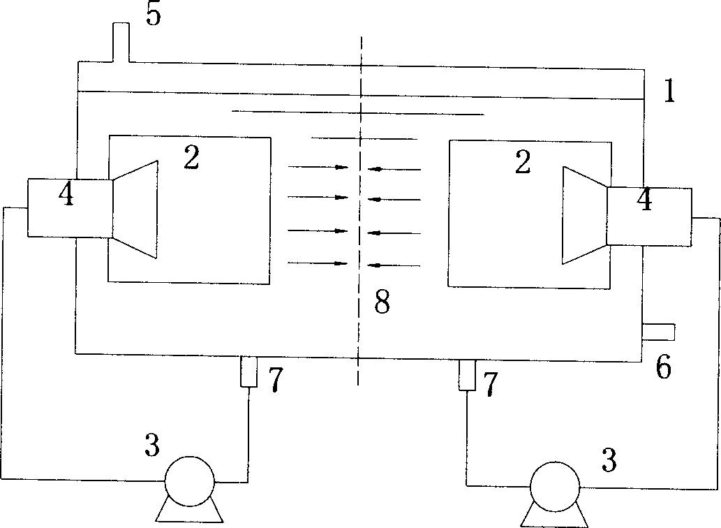
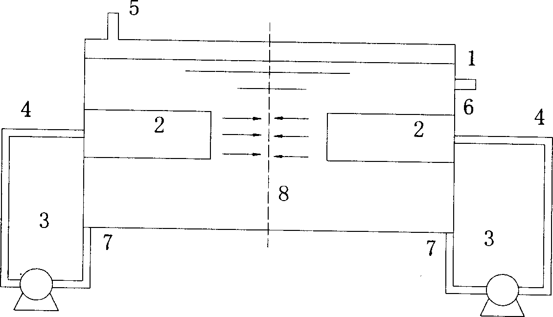
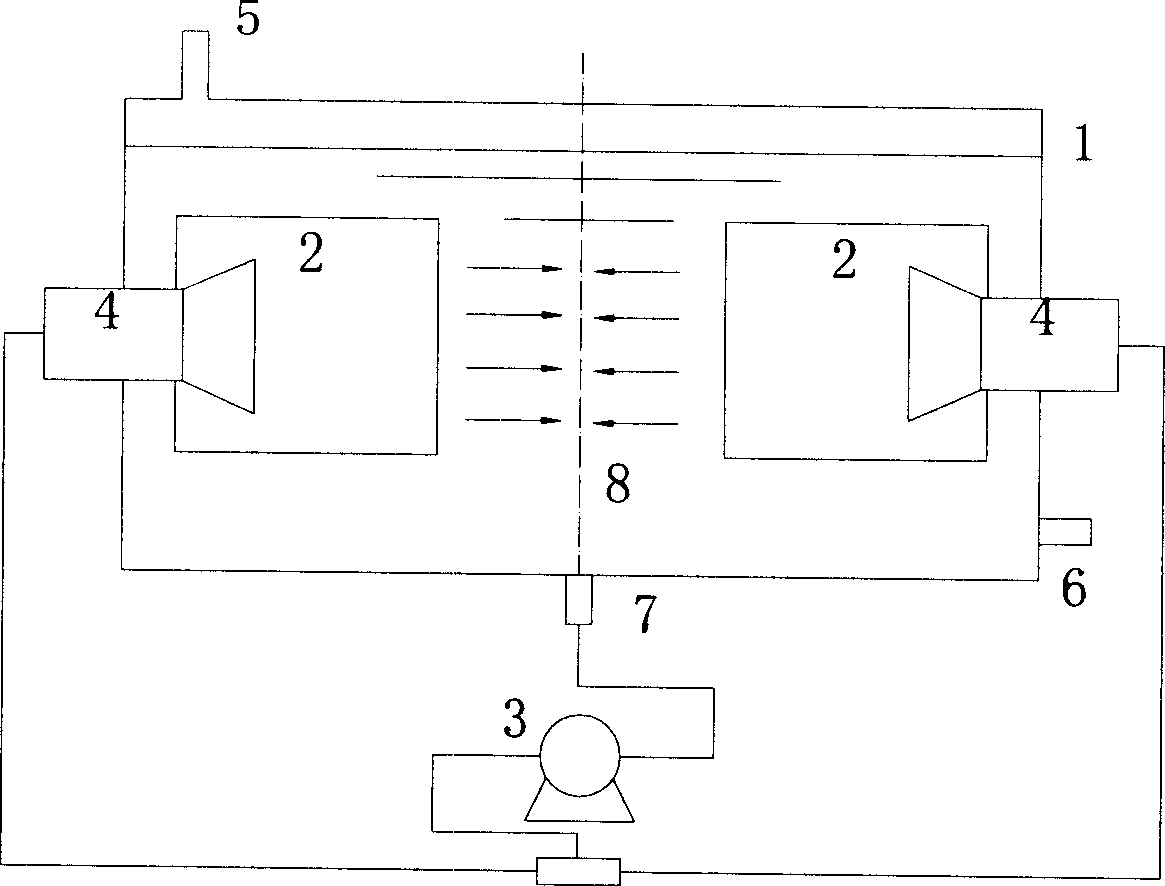
[0010] The structure and function of the impinging flow reactor of the present invention will be further described below in conjunction with the accompanying drawings.

[0011] figure 1 with figure 2 Two material circulation pumps are used in the image 3 with Figure 4 One material circulation conveying pump is used in the pump, and when a material circulation conveying pump is used, the materials at the outlet of the pump can be transported to the inlet of the diversion cylinder with a structure such as a tee. figure 1 with image 3 The connection between the outlet of the medium material delivery pump and the guide tube is designed as a conical tube. The angle of the conical tube can be between 30°C and 60°C. The purpose is to diffuse the reaction raw materials at the outlet of the guide tube to the entire guide tube Cross-section, there may be an annular structure between the guide tube and the tapered pipe, so that the materials in the reactor can form a certain circ...


PUM


Abstract

This invention relates to an impact flow reactor used for liquid phase reaction. The reactor is cylindrical form, pipe or quadratic structure, two draft tubes are fixed between reactors, and one or two pumps are set out of the reactor, the exit of the pump is corresponding set at feed side of the tube. The reactant impact with each other after conveyed by materials pump and high speed flow by draft tubes, so the mixing of the reactant is availably improved. The reactor in this invention maintains the advantage of high efficiency mixing and homogeneous reaction of the existing reactor, and some disadvantages of existing reactor is avoided. Its structure plan is facilitated and cost is reduced because of the replacement of pump cycling outside of the reactor of the screw propeller type structure, and engineering problem of shake, radial sealing failure brought by the screw propeller type structure is reduced. It is easy for maintenance, and its failure rate is low, so it is propitious to reaction process of industry scale.

Description

technical field [0001] The invention relates to an impingement flow reactor used in liquid-liquid phase reaction process in petroleum and chemical industry. Background technique [0002] For liquid-liquid reactions controlled by external diffusion in petroleum and chemical processes, the reactor is required to provide sufficient mixing space and maximum back-mixing for the reaction materials. [0003] The most commonly used reactor for liquid-liquid reaction in industry is a batch tank stirred reactor with stirring facilities. The disadvantage of this kind of reactor is that the back mixing in the reactor is uneven, the stirring efficiency is not high, and it is not suitable for continuous operation. The impinging flow reactor is a new type of chemical reactor. Because the materials in the reactor collide with each other, the contact area of ​​the materials is increased, the heat transfer and mass transfer rates are correspondingly increased, and the chemical reactions affe...

Claims


Application Information

Patent Timeline
Patent Type & Authority Applications(China)
IPC IPC(8): B01J14/00
Inventor 刘忠信黎元生勾连科
Owner CHINA PETROLEUM & CHEM CORP
Learn More