Soldered seal structure of power head part for thermal expansion valve

A technology of thermal expansion valve and power head, which is applied in the field of thermal expansion valve, can solve problems such as internal corrosion, increase of welding energy, and difficulty in one-time realization of the process, so as to achieve the effects of resisting pressure, preventing outer wall corrosion, and ensuring sealing

Inactive Publication Date: 2006-08-09
ZHEJIANG SANHUA CLIMATE & APPLIANCE CONTROLS GRP CO LTD
View PDF2 Cites 1 Cited by
  • Summary
  • Abstract
  • Description
  • Claims
  • Application Information

AI Technical Summary

Problems solved by technology

However, since the projection welding is directly connected together by melting the contact parts of two connected parts through resistance heat, the smaller the contact area of ​​the two parts, the greater the resistance heat generated per unit area, and the better the welding effect. The opposite is the opposite; therefore, the above solution sacrifices the welding quality per unit area while achieving multiple welding positions, which is undesirable to seal the heat-sensitive medium in the containing chamber with a plug, unless the welding energy is increased ; Moreover, the "cavity" pointed out in the CN 1058779C No. invention patent description will be formed between multiple welding positions to cause internal corrosion problems
[0004] On a deeper level, due to the heat expansion of the sealed heat-sensitive medium during welding, the pressure increases, which is very unfavorable for the relatively small welding part (0.2-1.5mm) formed by projection welding; based on the characteristics of projection welding, It is unavoidable to form a concave part around the projection welding part. Therefore, to prevent the outer wall from corroding, it is necessary to cover the projection welding part with anti-corrosion materials, which is difficult to realize in one process.

Method used


Image

  • Soldered seal structure of power head part for thermal expansion valve
  • Soldered seal structure of power head part for thermal expansion valve
  • Soldered seal structure of power head part for thermal expansion valve

Examples


Embodiment 1

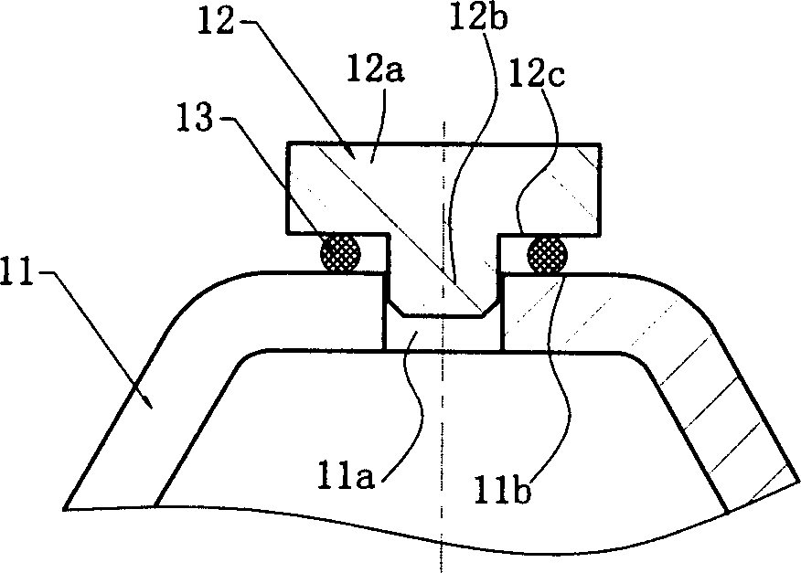
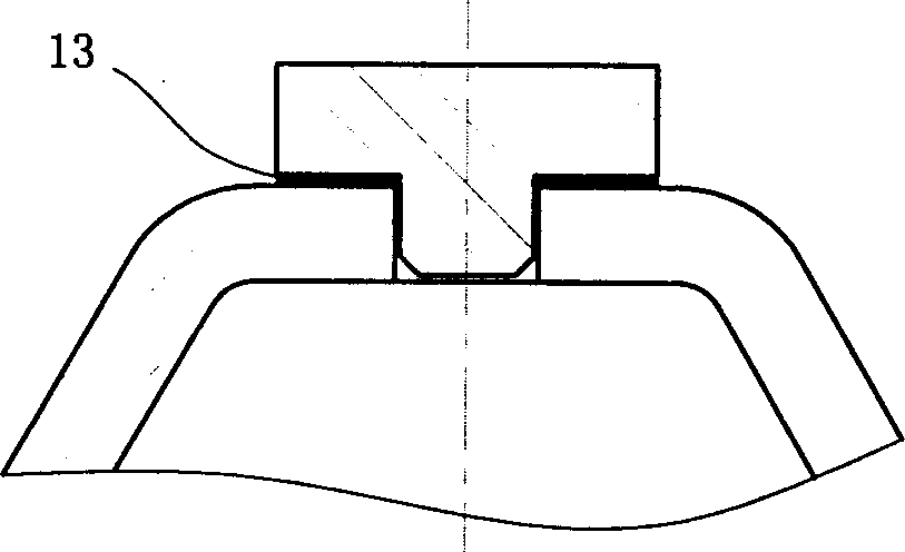
[0018] Such as Figure 1a , 1b As shown, a hole 11a is provided on the outer wall 11 as a filling hole, and the position adjacent to the hole 11a on its upper surface forms a plane as the outer wall welding surface 11b; The step surface adjacent to the head and the tail is the welding surface 12c; the solder 13 is placed between the outer wall welding surface 11b and the plug welding surface 12c; when welding, after the accommodating cavity is filled with a heat-sensitive medium, clamp it with a clamp The tail of the plug is pushed into the filling hole and pressed tightly (during which the head of the plug cooperates with the filling hole to play a guiding role), and the resistance heat is generated by electrification to melt the solder to form a seal, completing the connection between the plug and the outer wall, because the solder evenly fills the plug and the The gap between the outer walls not only plays a role of sealing, but also plays a role of anti-corrosion, which is...

Embodiment 2

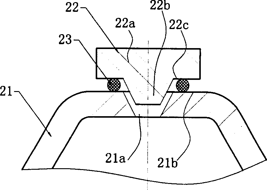
[0020] Such as Figure 2a , 2b As shown, a taper hole 21a is set on the outer wall 21 as a filling hole, and a plane adjacent to the taper hole 21a is formed on its upper surface as an outer wall welding surface 21b; The frustum-shaped portion serves as the head 22b, and the stepped surface adjacent to the head and tail is the welding surface 22c; the solder 23 is placed between the outer wall welding surface 21b and the plug welding surface 22c; the welding is the same as in the first embodiment.

Embodiment 3

[0022] Such as Figure 3a , 3b Shown, be to offer variable-diameter hole 31a on outer wall 31 as filling hole, and its upper section is taper hole, and its lower section is round hole, and the position that the upper surface of outer wall 31 is adjacent to variable-diameter hole 31a forms plane as outer wall welding surface 31b; 32 is in the shape of a truncated cone, its upper cylindrical part is used as the tail part 32a, the lower end of the truncated cone part is used as the head part 32b, and the step surface adjacent to the head part and the tail part is the welding surface 32c; the solder 33 is placed on the outer wall welding surface 31b and the plug Between the welding surfaces 32c; the welding is the same as in the first embodiment.


PUM


Abstract

This invention is related to a brazing and sealing structure of dynamic head component of thermal expansion valve. The dynamic head component is consists of a stopper and a cavity which used to accommodate the thermal-sensitive medium. The cavity has holes in its ektexine and the medium can be added into the cavity through the holes. The stopper is used to plug the holes so the medium is sealed in the cavity. Its characteristics are placing brazing filler metal between the stopper and the ektexine and brazing to form a seal, so the thermal-sensitive medium is sealed in the cavity reliably. The program uses the method of brazing to put brazing filler metal between the stopper and ektexine, and melting down the brazing filler metal using the thermal resistance, and make the filler infiltrated into the stopper and the ektexine and realize the connection of the two parts. It is not only helpful for ensuring the seal and preventing the outer wall from being corrupted, but it also can resist the pressure effectively that produced by the heat expansion of the medium, and it is helpful for molding in one time in process.

Description

【Technical field】 [0001] The invention relates to a thermal expansion valve suitable for an air-conditioning system, especially a structure for sealing a heat-sensitive medium in an accommodating cavity by sealing a filling hole of a power head (also called an air box head) with a plug. 【Background technique】 [0002] The existing thermal expansion valve suitable for air-conditioning systems is clearly recorded in the invention patent specification with the notification number CN 1058779C. The structure in the cavity is described in detail, and the analysis and induction of the prior art in this document are as follows: ①Project welding is performed between the edge around the hole and the conical surface of the plug, because a concave part is formed around the convex welding part, so Water accumulation (condensation water, etc.) is likely to occur in the concave part, and there is a problem of corroding the outer wall of the cover; ② The plug is tack welded by projection we...

Claims


Application Information

Patent Timeline
Patent Type & Authority Applications(China)
IPC IPC(8): B23K33/00
Inventor 杜又德
Owner ZHEJIANG SANHUA CLIMATE & APPLIANCE CONTROLS GRP CO LTD
Why Eureka
Try Eureka