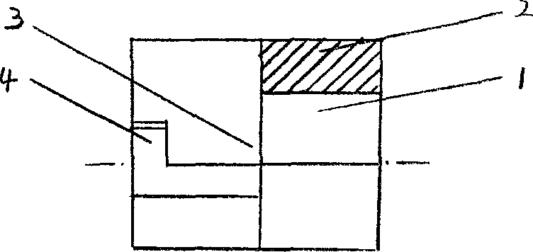
Piston-type IC engine of continuous variable valve timing and gas-distributing mechanism
A valve train, valve timing technology, applied in the direction of machine/engine, mechanical equipment, engine components, etc., can solve the problem of not being able to control the duration of intake and exhaust valves and valve lift, limiting the effective power and thermal efficiency of internal combustion engines, etc.
- Summary
- Abstract
- Description
- Claims
- Application Information
AI Technical Summary
Problems solved by technology
Method used
Image
Examples
Embodiment Construction
[0066] Figure 7 Among them, it consists of a hydraulic tappet (7), a continuously variable valve timing actuator (8), a main intake camshaft (9), a sliding ball column (10), an auxiliary intake camshaft (11), and a gimbal ( 12), the basic composition structure of the moving part of the valve train composed of the valve guide (14) and the intake valve (15).
[0067] Figure 8 Among them, it consists of a hydraulic tappet (7), a continuously variable valve timing actuator (8), a main intake camshaft (9), a sliding ball column (10), an auxiliary intake camshaft (11), and a gimbal ( 12), rocker arm (13), the basic composition structure of the rocker arm valve train moving part that valve guide (14) and intake valve (15) form.
PUM
 Abstract
Description
Claims
Application Information
 - R&D
- Intellectual Property
- Life Sciences
- Materials
- Tech Scout
- Unparalleled Data Quality
- Higher Quality Content
- 60% Fewer Hallucinations
Browse by: Latest US Patents, China's latest patents, Technical Efficacy Thesaurus, Application Domain, Technology Topic, Popular Technical Reports.
© 2025 PatSnap. All rights reserved.Legal|Privacy policy|Modern Slavery Act Transparency Statement|Sitemap|About US| Contact US: help@patsnap.com


