

Olefin polymerizing reactor
An olefin polymerization and reactor technology, which is applied in the field of reactors to achieve the effects of strengthening practical significance, reducing ash content and improving product quality
- Summary
- Abstract
- Description
- Claims
- Application Information
AI Technical Summary
Problems solved by technology
Method used
Image

Examples
Embodiment 1
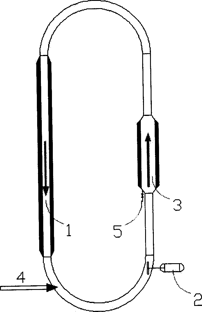
[0035] A polymerization reactor for polyethylene (PE) production, such as figure 1 shown. The reactor is composed of three straight pipes, two curved pipes, and an enlarged section connected in sequence. An axial flow pump or centrifugal pump 2 is installed at the lower end of the ascending pipe. Under the action of the axial flow pump or centrifugal pump, the slurry in the pipe 1 High-speed circulation is made inside, and the flow direction is shown by the arrow in the figure. The reaction material 4 is added from the position shown in the figure by means of multi-point feeding. An expansion section 3 is provided in the first ascending pipe, and a discharge device 5 is provided at the bottom of the expansion section 3. The discharge device adopts a settling tube, and the material is deposited in the settling tube, and then discharged intermittently or continuously. Both the ring pipe area and the expansion section are equipped with heat exchange devices.
[0036] The relev...
Embodiment 2
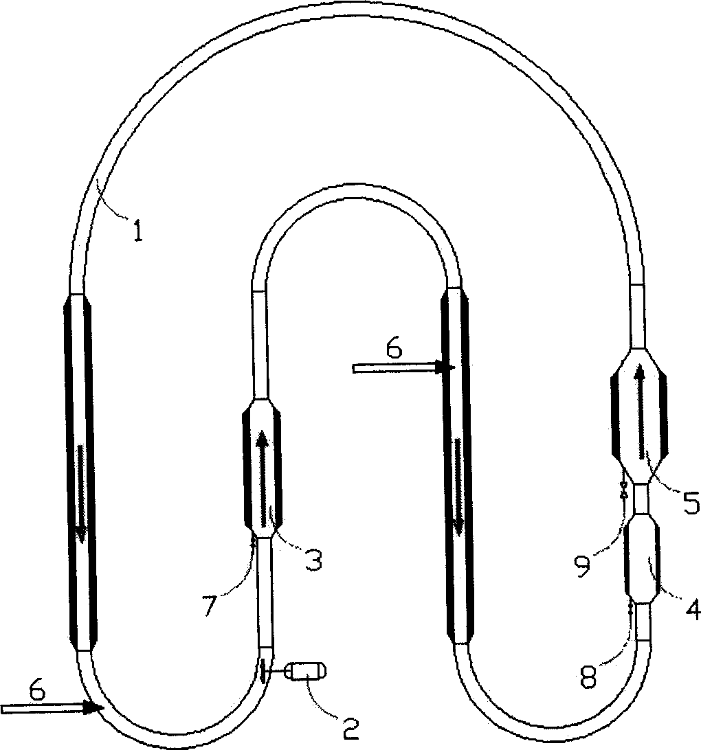
[0040] A polymerization reactor for polypropylene (PP) production, such as figure 2shown. The reactor is composed of seven straight pipes, four curved pipes, and three enlarged sections connected sequentially. An axial flow pump or centrifugal pump 2 is installed at the lower end of the first upward pipe. Under the action of the axial flow pump or centrifugal pump , the slurry circulates at a high speed in the pipeline 1, and the flow direction is shown by the arrow in the figure. The reaction material 6 is fed from the two positions shown in the figure by means of multi-point feeding. Two enlarged sections 3 and 4 are arranged in the first ascending pipe, and an enlarged section 5 is arranged in the second ascending pipe. Three settling tubes 7, 8, 9 are arranged at the bottom of the three expanding sections 3, 4, 5, and materials are deposited in the settling tubes, and then discharged intermittently or continuously. Along the direction of fluid movement, the inner diame...
Embodiment 3
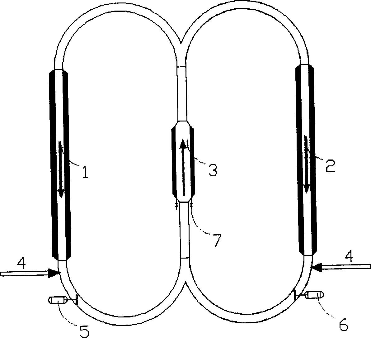
[0045] A polymerization reactor for polyethylene production, such as image 3 shown. The reactor is composed of four straight pipes, four curved pipes, and an enlarged section connected sequentially. Axial flow pumps or centrifugal pumps 5 and 6 are installed at the lower ends of the two downgoing pipes. Under the action of the axial flow pump or centrifugal pump , the slurry circulates at a high speed in the pipes 1 and 2, and the flow direction is shown by the arrow in the figure. Reaction mass 4 is added from the two positions shown. There is an expanding section 3 in the ascending pipe, and three settling tubes 7, 8, 9 are arranged at the bottom of the expanding section, and materials are deposited in the settling tubes, and then discharged intermittently or continuously. Both the ring pipe area and the expansion section are equipped with heat exchange devices.
[0046] The relevant parameters of the expansion section are shown in the table below:
[0047] I...
PUM
| Property | Measurement | Unit |
|---|---|---|
| angle | aaaaa | aaaaa |
| angle | aaaaa | aaaaa |
Abstract
Description
Claims
Application Information