Cooling system for computer hardware

A computer and circuit board technology, applied in the field of two-way heat solutions, can solve the problems of no change in the cooling system, lower overall efficiency of the cooling system, and more air, so as to achieve the effect of effective cooling system and increase of effective surface area

A computer and circuit board technology, applied in the field of two-way heat solutions, can solve the problems of no change in the cooling system, lower overall efficiency of the cooling system, and more air, so as to achieve the effect of effective cooling system and increase of effective surface area

CN1818827AActive Publication Date: 2006-08-16NVIDIA CORP

Image

  • Cooling system for computer hardware
  • Cooling system for computer hardware
  • Cooling system for computer hardware

Examples


Embodiment Construction

[0018] Reference directions used in describing components, such as top and bottom, are for convenience and are not intended to limit the embodiments of the present invention in any way.

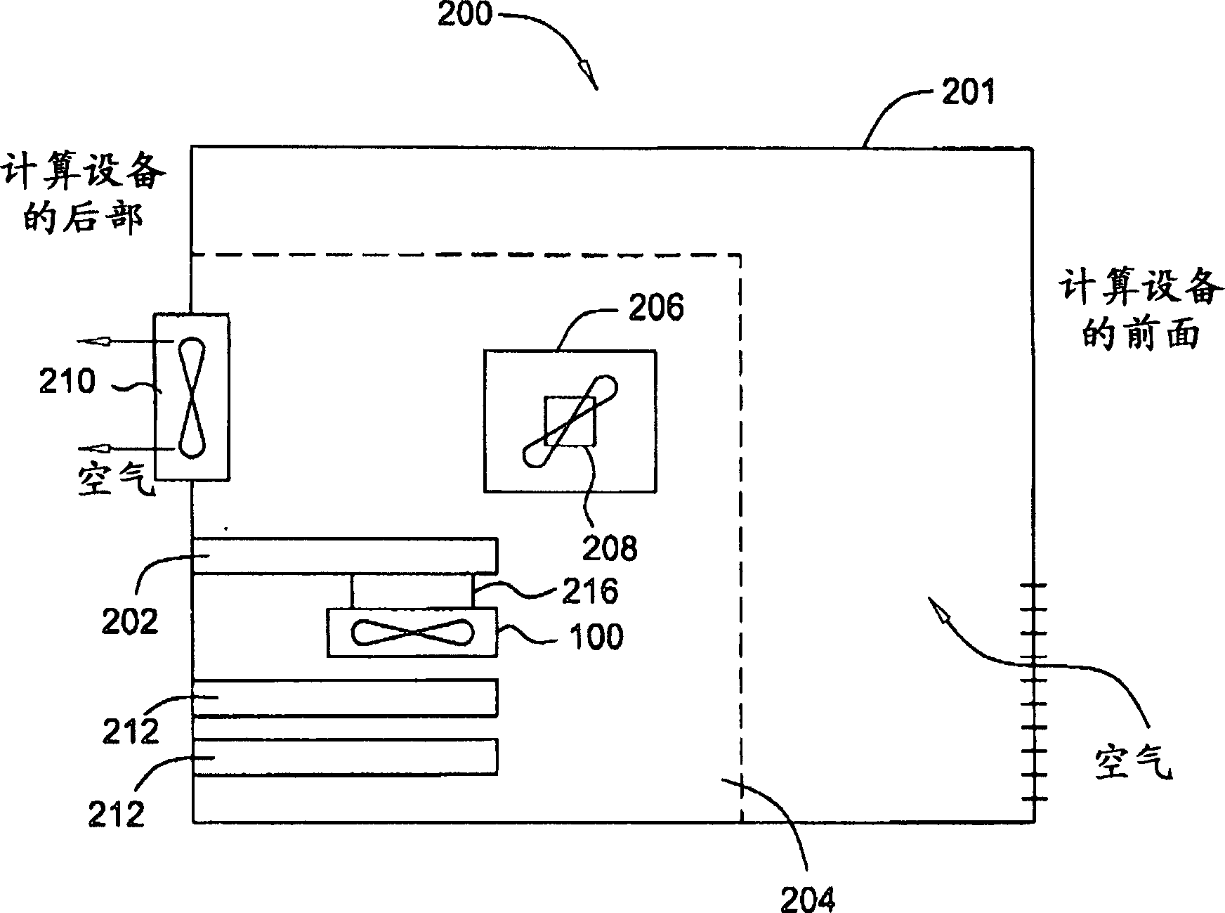
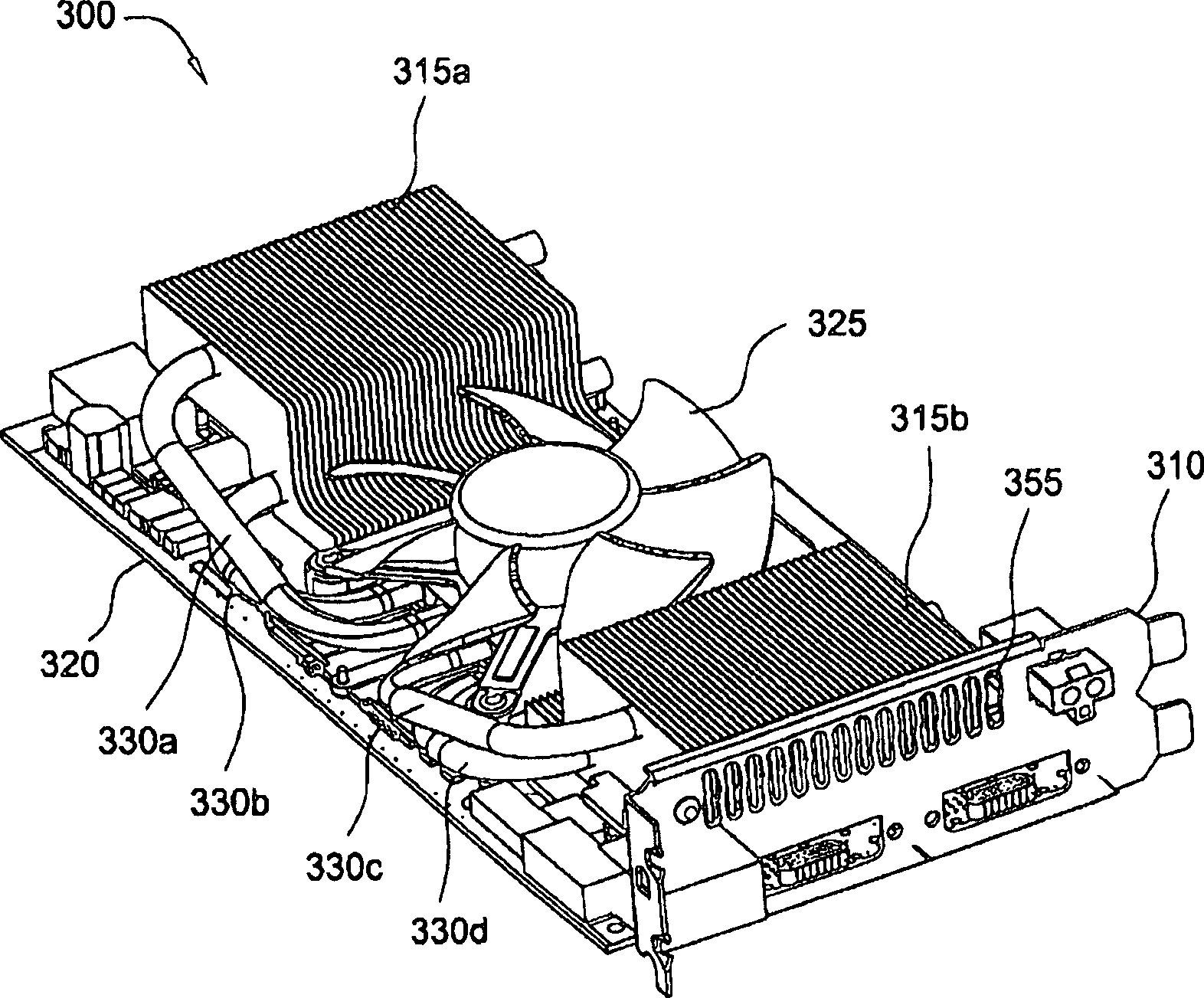
[0019] Figure 3A - I are views of a cooling system 300 or components thereof for cooling a heat-generating electronic device, according to an embodiment of the present invention. The cooling system covers 305 from the Figure 3A and 3D-3F are omitted for ease of illustration. refer to Figure 3B , as shown, the cooling system 300 is thermally and structurally coupled to a printed circuit board (PCB), such as a graphics card 320 or figure 2 graphics card 202 . Graphics card 320 mounts GPU 345 and other components such as memory units 347a-d on the top side. Graphics card 320 may also include a memory unit (not shown) on the bottom side. Preferably, graphics card 320 is configured to connect to a personal computer (such as figure 2 computing device 200). Furthermore, the cooling system...


PUM


Abstract

The present invention represents a significant advancement in the field of cooling systems for computer hardware. In one embodiment, a system for cooling a heat-generating electronic device is provided. The system is mountable to a first side of a circuit board. The system includes a first set of fins, a fan operable to force air through the first set of fins, and a first heat pipe to conduct heat from the heat-generating electronic device to the first set of fins. One advantage of the disclosed cooling system is that it more equally distributes heat across the fins and more equally distributes airflow across surfaces of the fins. Thus, the design increases the effective area of the fin surfaces used in for transferring heat from the heat-generating electronic device to the air, resulting in a more efficient cooling system.

Description

[0001] Cross References to Related Applications [0002] This application claims priority to US Provisional Application No. 60 / 645,997 (Attorney Docket No. NVDA P001569), filed January 21, 2005, the entire contents of which are incorporated by reference. technical field [0003] The present invention relates generally to cooling systems for computer hardware, and more specifically, to a two-way thermal solution for computer hardware. Background technique [0004] FIG. 1 is an isometric view of a prior art cooling system 100, such as used to cool heat-generating electronic devices, such as graphics processing units (GPUs), in computer systems. As shown, the cooling system 100 specifically includes a blower / fan 106 , a heat sink 109 and a base plate 111 . Typically, the cooling system 100 is thermally coupled to the GPU, eg, using a thermal adhesive or grease with thermal properties, so as to transfer heat generated by the GPU to the base plate 111 . Cooling system 100 may i...

Claims


Application Information

Patent Timeline
16 Aug 2006
Publication
CN1818827A
IPC
G06F1/20
CPC
H01L23/467; H01L2924/0002; H01L23/427; G06F1/20; H01L2924/00
Inventors
Z·斯特凡诺斯基