Organic electroluminescence device and method of producing the same

An electroluminescent device, organic light-emitting layer technology, applied in the direction of electroluminescent light source, electric light source, lighting device, etc.

Inactive Publication Date: 2006-08-30
TOYOTA IND CORP
View PDF1 Cites 1 Cited by
  • Summary
  • Abstract
  • Description
  • Claims
  • Application Information

AI Technical Summary

Problems solved by technology

The present inventio

Method used


Image

  • Organic electroluminescence device and method of producing the same

Examples


Embodiment 1

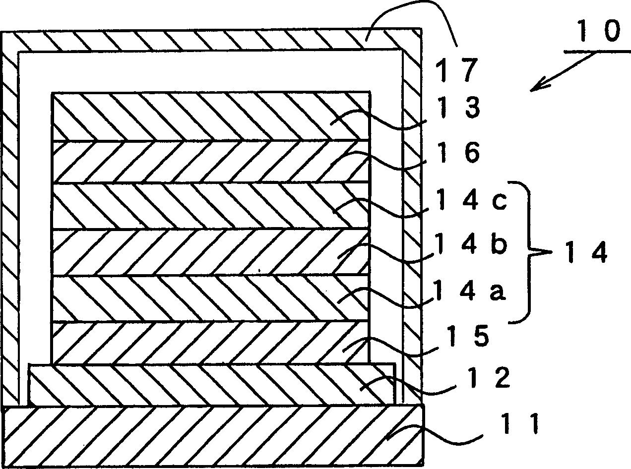
[0041] An anode layer 12 formed of an ITO layer having a thickness of 150 nm was formed on one surface of a transparent glass substrate 11, and the substrate / anode layer structure was subjected to substrate cleaning in which alkali cleaning and pure water cleaning were performed successively, and after being After drying, ultraviolet ozone cleaning is performed.

[0042] Then, the anode layer 12 was treated with plasma of an oxygen-argon mixed gas having an argon content of 10 vol % for two minutes at a pressure of 2 Pa and a radio frequency power of 200 W. Before the plasma treatment, the work function of the surface of the anode layer 12 was 4.6 eV, and after the plasma treatment, its work function was about 5.7 eV.

[0043] After the anode layer 12 is subjected to plasma treatment, by utilizing a vapor deposition device such as a graphite crucible at a deposition rate of 0.1 nm / s and about 5.0×10 -5 A vacuum degree of Pa deposited a TPTE layer of an amine-based low-molecul...

Embodiment 2-9

[0054]For the production of the organic EL devices of Examples 2-9, except that the argon content in the oxygen-argon mixed gas used for plasma treatment is 30vol%, 43vol%, 49vol%, 55vol%, 59vol%, 69vol%, 82vol% % and 89 vol%, the others are the same as those of the organic EL device 10 of Example 1. The work function of the surface of the anode layer 12 after plasma treatment is 5.7-5.9 eV. As in the case of the power coefficient of the organic EL device 10 of Example 1, the power coefficients of the organic EL devices 10 of Examples 2-9 were measured before and after the heating test and the light irradiation test. Table 1 also shows the results of the retention ratios of the power coefficients of the organic EL devices of Examples 2-9.

[0055] heating test

light test

Example

Argon content (vol%)

Power Coefficient Retention

Power Coefficient Retention

1

10

100%

70%

2

30

101%

80%

...


PUM

PropertyMeasurementUnit
Thicknessaaaaaaaaaa
Thicknessaaaaaaaaaa

Abstract

An organic EL device includes an anode layer, a hole injection and transport layer, an organic light-emitting layer and a cathode layer. The anode layer is formed of metal-oxide based material which is electrically conductive. The hole injection and transport layer is formed on the anode layer using material other than phthalocyanine metal complex. The organic light-emitting layer is formed on the hole injection and transport layer. The cathode layer is formed on the organic light-emitting layer. After the organic EL device is heated for 150 hours at the temperature of 85 DEG C, the retention rate of its power efficiency is equal to or more than 80 %.

Description

Background of the invention [0001] The present invention relates to an organic electroluminescent device and a method for producing such a device. [0002] Organic electroluminescence devices are used, for example, in displays and lighting units as planar light emitting devices. For convenience, the organic electroluminescent device is hereinafter referred to as an organic EL device. The basic structure of an organic EL device includes a transparent anode layer, an organic light-emitting layer, and a cathode layer laminated in this order on a transparent substrate such as a glass substrate. An organic EL device may include a hole injection and transport layer interposed between a transparent anode layer and an organic light emitting layer. The organic EL device may further include an electron injection and transport layer interposed between the cathode layer and the organic light emitting layer. [0003] In an organic EL device formed of a hole injection and transport layer...

Claims


Application Information

Patent Timeline
IPC IPC(8): H01L51/50H01L51/54H01L51/56H05B33/12H05B33/10
Inventor 山本一郎村崎孝则
Owner TOYOTA IND CORP
Why Eureka
Try Eureka