Device and method for manufacturing panel with embossing on surface

A technology of embossing and panel parts, which is applied in the field of panel device devices, and can solve problems such as unsolvable problems

Inactive Publication Date: 2006-09-06
FORHOUSE CORPORATION
View PDF0 Cites 11 Cited by
  • Summary
  • Abstract
  • Description
  • Claims
  • Application Information

AI Technical Summary

Problems solved by technology

However, if the substrate is set to require a certain thickness (

Method used


Image

  • Device and method for manufacturing panel with embossing on surface
  • Device and method for manufacturing panel with embossing on surface
  • Device and method for manufacturing panel with embossing on surface

Examples


Embodiment Construction

[0019] In order to describe the structure and characteristics of the present invention in detail, the following preferred embodiments are given and illustrated in conjunction with the drawings as follows:

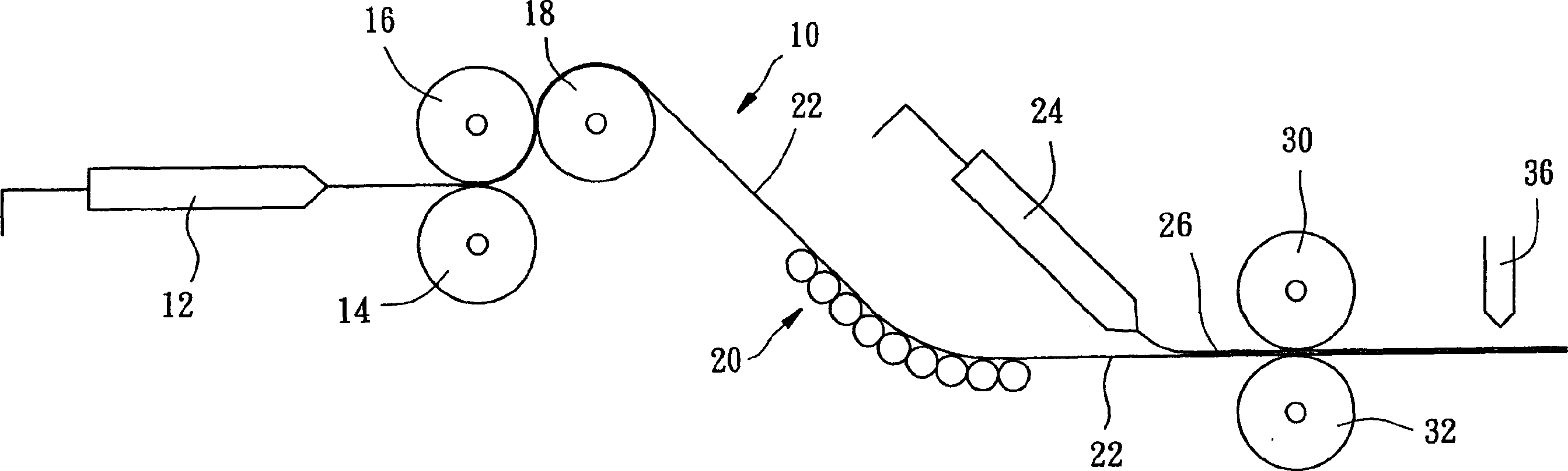
[0020] see figure 1 As shown, the device for manufacturing a plate with embossing on the surface provided by a preferred embodiment of the present invention includes: a base material supply device 10, a cooler 20, a skin layer supply device 24, a rolling press device and cutting device 36.

[0021] The substrate supply device 10 provides a solid elongated substrate 22 and includes a conventional extruder 12 and three rollers 14 , 16 , 18 . The extruder 12 can provide a plastic material in a molten state, such as polycarbonate (Polycarbonate, PC), polymethyl methacrylate (Polymethyl methacrylate, PMMA), cycloolefin polymer (Cyclic Olefins Polymer, COP) or It is a cyclic olefin copolymer (Cyclic Olefins Copolymer, COC). The rollers 14 , 16 , 18 are arranged at the outlet ...


PUM


Abstract

The invention relates to a device for producing the plate with figure on surface and relative method, which comprises: a basic material supplier, a condenser, a surface layer supplier, a rolling compression device, and a slicing device. Wherein, the basic material supplier provides basic material in fusing condition; said condenser cools said basic material to solid state; said surface layer supplier supplies a surface layer in fusion state on said basic material, then via said roller compression device to emboss said basic material and surface layer, to form a figure on said surface; and the slicing device slices the basic material and surface layer to attain the sheets in dual number.

Description

technical field [0001] The invention relates to a tool mechanism, in particular to a device and method for manufacturing a board with embossing on the surface. Background technique [0002] Existing methods for forming composite materials include extrusion, injection molding, and compression molding. [0003] Generally, the most commonly used molding method is injection molding, and its main steps are: feeding powdery or granular plastic raw materials into an injector (injector), the plastic raw materials are heated and melted in the injection machine, and injected by an injection molding machine. The nozzle is injected into the cavity of a mold. After cooling, the mold is opened to obtain a component with a predetermined shape. The advantage of the injection molding method is that it can form components with complex shapes or fine structures, but when forming large components, the cost of the mold will increase, and there will be residual stress in the components. [000...

Claims


Application Information

Patent Timeline
IPC IPC(8): B29C59/04
Inventor 潘重华潘重德李俊锜
Owner FORHOUSE CORPORATION
Why Eureka
Try Eureka