Photoelectric converter and method for manufacturing same
A technology of photoelectric conversion elements and conductors, applied in electrical components, photovoltaic power generation, circuits, etc., can solve problems such as complex manufacturing processes, unsuitable for long-term use, and adverse effects of pigments
- Summary
- Abstract
- Description
- Claims
- Application Information
AI Technical Summary
Problems solved by technology
Method used
Image

Examples
no. 1 Embodiment approach
[0076] Hereinafter, the first embodiment of the present invention will be described in detail based on examples.
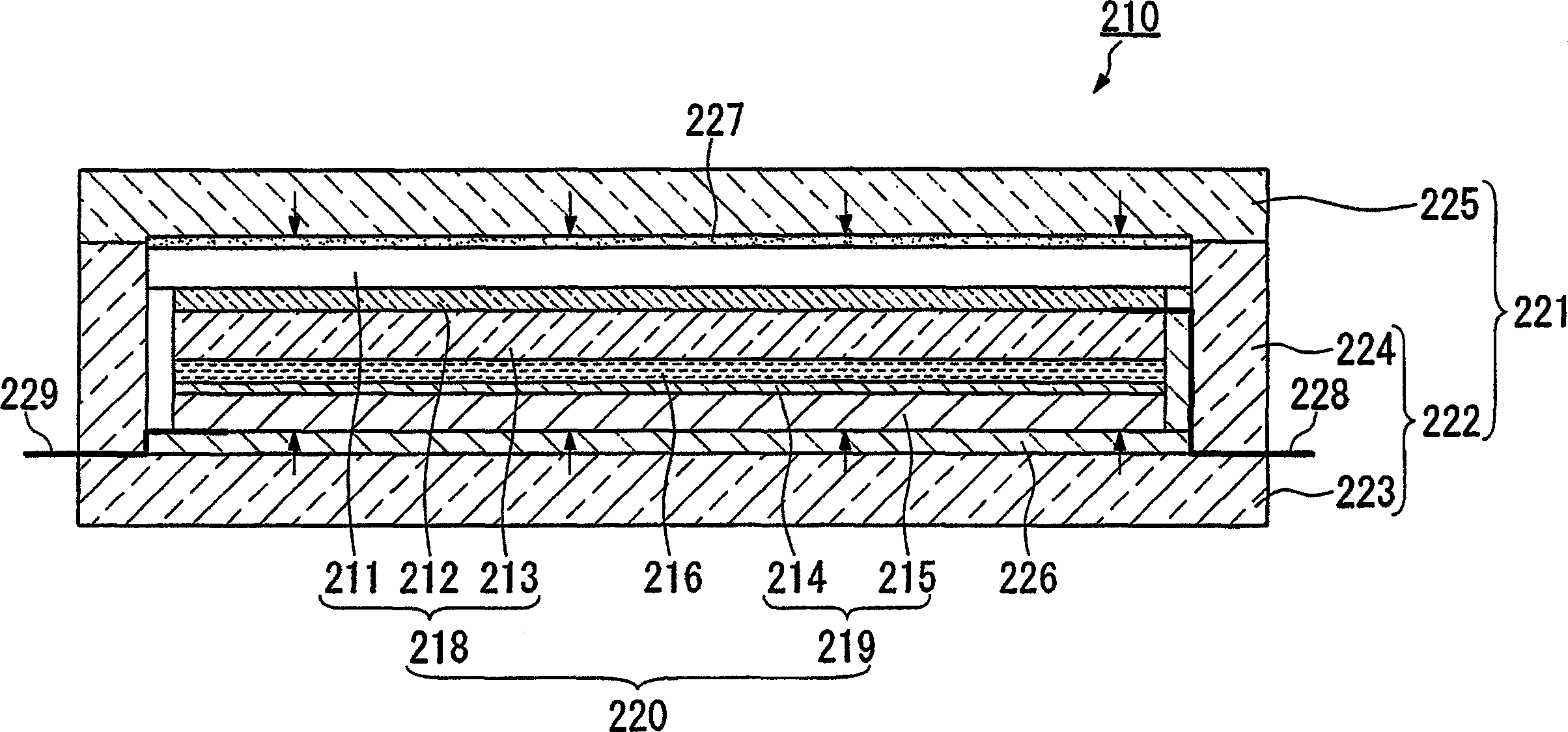
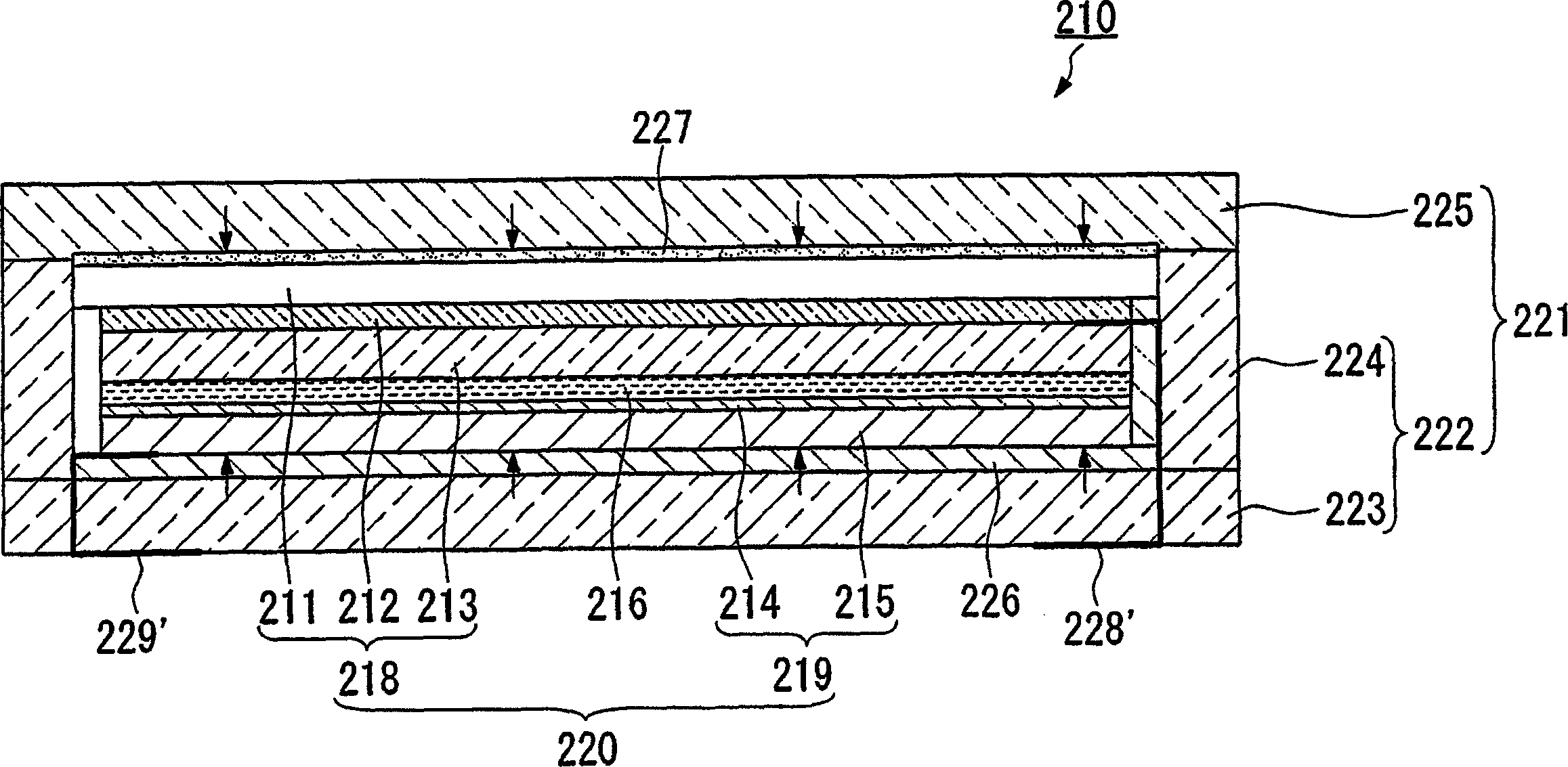
[0077] figure 2 It is a schematic cross-sectional view showing an example of the photoelectric conversion element according to the first embodiment of the present invention.
[0078] This dye-sensitized solar cell (photoelectric conversion element) 210 is provided with a working electrode (also called a window electrode) having a porous oxide semiconductor layer (also called an oxide electrode) 213 carrying a sensitizing dye on its surface. 218 , a counter electrode 219 disposed opposite to the porous oxide semiconductor layer 213 side of the working electrode 218 , and at least a part of the electrolyte layer 216 located between the two electrodes. The working electrode 218 is composed of, for example, a first substrate 211 and a transparent conductive film 212 and an oxide electrode 213 sequentially arranged thereon. One counter electrode 219 is composed of, ...
no. 2 Embodiment approach
[0105] recorded above Figure 4 The photoelectric conversion element 250 according to the first embodiment of the present invention is shown. This photoelectric conversion element 250 has been improved based on two main viewpoints described below.
[0106] First, the effect of heat applied when bonding the electrodes on the dye adsorbed on the dye-sensitized semiconductor electrode can be suppressed, and the weather resistance during long-term use is excellent, and the electrolyte solution can be easily injected.
[0107] That is, according to Figure 4 Since heat is not directly applied to the two electrodes, that is, the working electrode 258 and the counter electrode 259, the above-mentioned influence of heat on the pigment can be avoided. Furthermore, by dropping the electrolytic solution onto the dye-sensitized semiconductor electrode 253 and sandwiching it, the laminated body 260 in which the electrolytic solution is sandwiched between the working electrode 258 and the...
no. 3 Embodiment approach
[0144] The third embodiment of the present invention will be described in detail below based on examples.
[0145] Image 6 A plan view showing a dye-sensitized solar cell as an example of a photoelectric conversion element according to a third embodiment of the present invention, Figure 7 yes Image 6 Sectional view of line A-A.
[0146] This dye-sensitized solar cell 401 is formed by sealing a plurality of stacked bodies 402 arranged in a flat state in a casing 403 .
[0147] The laminated body 402 is composed of a working electrode 421 provided with a porous oxide semiconductor layer 421a on one surface, and a counter electrode 422 disposed opposite to the porous oxide semiconductor layer 421a, so that the working electrode 421 and the counter electrode 422 It is formed by overlapping with an electrolyte layer (not shown) sandwiched between them.
[0148] The aforementioned active pole 421 has: a transparent substrate 421b such as a glass substrate, a light-transmittin...
PUM
| Property | Measurement | Unit |
|---|---|---|
| Thickness | aaaaa | aaaaa |
Abstract
Description
Claims
Application Information
 - R&D
- Intellectual Property
- Life Sciences
- Materials
- Tech Scout
- Unparalleled Data Quality
- Higher Quality Content
- 60% Fewer Hallucinations
Browse by: Latest US Patents, China's latest patents, Technical Efficacy Thesaurus, Application Domain, Technology Topic, Popular Technical Reports.
© 2025 PatSnap. All rights reserved.Legal|Privacy policy|Modern Slavery Act Transparency Statement|Sitemap|About US| Contact US: help@patsnap.com