Satellite laser range-measurement system based on tilt correction

A satellite laser ranging and tilt correction technology, which is used in radio wave measurement systems, measurement devices, and electromagnetic wave re-radiation, etc., can solve the problems of poor fast target pointing accuracy, insufficient satellite tracking accuracy, and low utilization of laser energy. Achieve the effect of improving the tracking accuracy, reducing the corresponding requirements of the divergence angle, and improving the ability

Inactive Publication Date: 2006-09-13
INST OF OPTICS & ELECTRONICS - CHINESE ACAD OF SCI
View PDF0 Cites 18 Cited by
  • Summary
  • Abstract
  • Description
  • Claims
  • Application Information

AI Technical Summary

Problems solved by technology

The disadvantage of this satellite laser ranging scheme is that satellites at different altitudes are affected by different perturbations, and their orbit prediction accuracy is also different. The prediction accuracy of high-orbit satellites is better than that of low-orbit satellites. Accuracy makes the tracking accuracy of satellites insufficient when performing satellite laser ranging, especially for low-orbit (orbital height < 800km), the fast target pointing accuracy will be worse
[0004] Xiang Qingge, Wei Zhibin, Cheng Bohui, Qu Feng, Wang Tanqiang and others designed an adjustable divergence angle system ("Design of divergence angle system for satellite laser range finder", 2004). For low-orbit satellites, by increasing the divergence The angle sacrifices the echo intensity to increase the probability of capture, but this puts forward higher requirements on the output power of the laser light source, and the utilization rate of laser energy is low, there are still too many uncertain factors, and there is no key to solving the problem

Method used


Image

  • Satellite laser range-measurement system based on tilt correction
  • Satellite laser range-measurement system based on tilt correction
  • Satellite laser range-measurement system based on tilt correction

Examples


Embodiment Construction

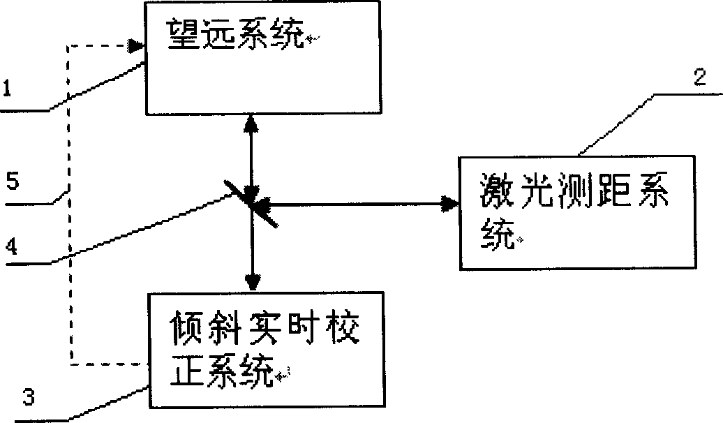
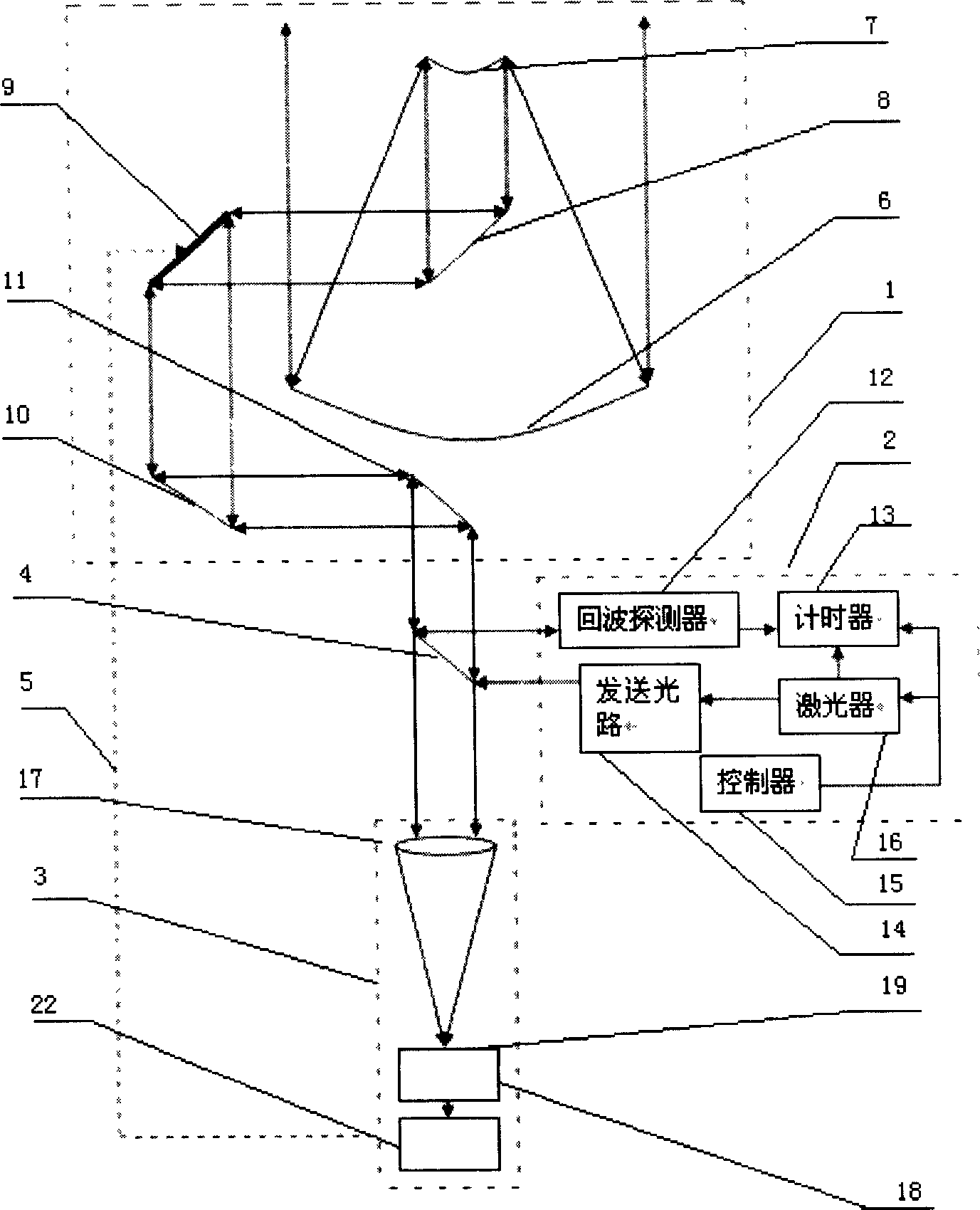
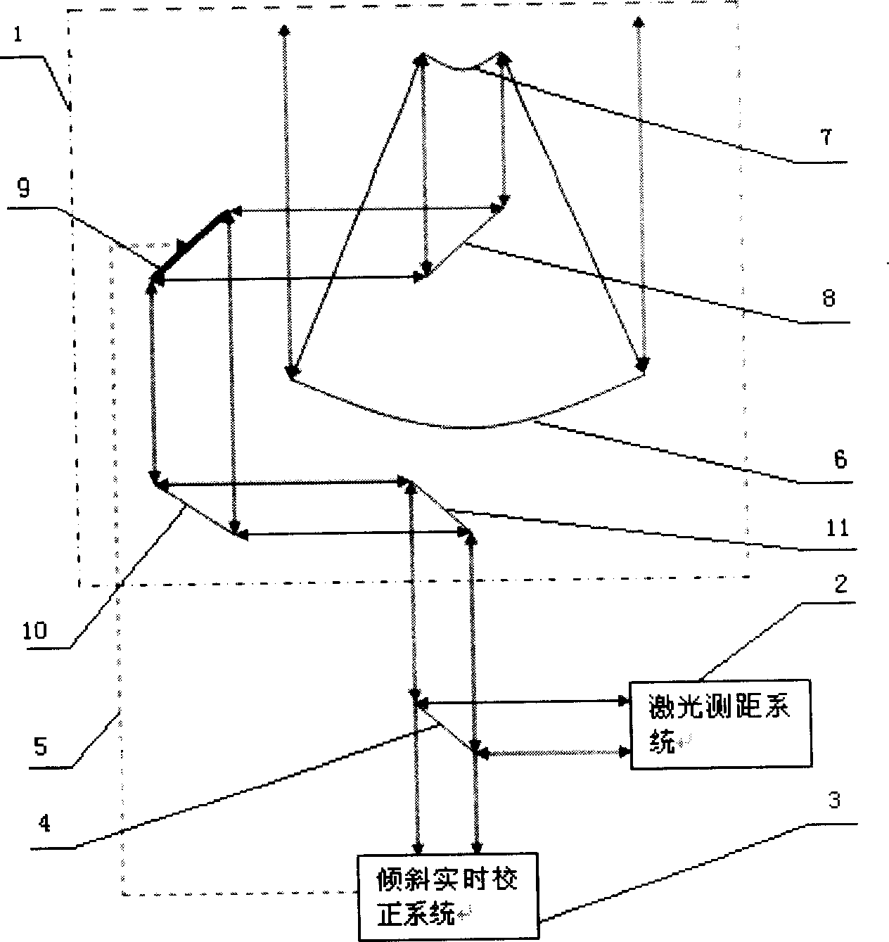
[0023] Such as figure 1 , 2 As shown, the entire satellite laser ranging system based on tilt correction is composed of three subsystems, which are receiving telescope system 1, laser ranging system 2, and tilt real-time correction system 3. The sunlight reflected by the satellite enters the Coude room from the receiving telescope system Finally, after the light wave passes through the beam splitter 4, it is transmitted to the tilt real-time correction system 3 for wavefront detection. After the wavefront restoration and control algorithm, the high-speed tilting mirror in the receiving telescope system is controlled by the control loop 5 to perform real-time closed loop, and then the laser is turned on. Ranging sending / receiving system 2, which sends laser with a specific wavelength to perform satellite laser ranging. Since the tilt has been corrected, the pointing accuracy of the telescope has been improved by an order of magnitude. At this time, the laser ranging can greatl...


PUM


Abstract

A satellite laser distance measurement system based on tilt calibration is featured as setting high speed tilt reflector in telescoping unit, using tilt tracking transducer to carry out wave front detection on light wave received by receiving telescope, outputting calibration control signal to high speed tilt mirror in telescope by high speed processor after error signal is restored, starting up satellite laser distance measurement system in telescoping unit to send out laser with specific wavelength for carrying out satellite laser distance measurement after tilt closed loop real time calibration is finished.

Description

technical field [0001] The invention is a system for high-precision laser satellite ranging, which is used for real-time correction of atmospheric turbulence and tilt tracking jitter introduced by the telescope itself so as to improve the pointing accuracy of the satellite. Background technique [0002] Satellite Laser Ranging (SLR) is a technical means initiated by NASA in the early 1960s to use space technology to study geodynamics, geodesy, geophysics and astronomy. The characteristic of the laser ranging satellite is that a corner reflector is installed on the surface of the satellite to reflect the laser emitted by the ground station. The ground station uses the receiving telescope to receive the laser returned from the satellite corner reflector, and uses the time interval counter to measure the time required for the laser to go back and forth, so that the distance from the ground station to the satellite can be accurately obtained. In the calculation process, the spe...

Claims


Application Information

Patent Timeline
Patent Type & Authority Applications(China)
IPC IPC(8): G01S17/08
Inventor 饶长辉魏凯张雨东张昂吴碧琳周璐春
Owner INST OF OPTICS & ELECTRONICS - CHINESE ACAD OF SCI
Why Eureka
Try Eureka