Anti-glare film, manufacturing method of anti-glare film, anti glaring anti-reflection film, polarizing plate, and display

An anti-glare and glare technology, applied in the direction of polarizing element, diffusing element, transportation and packaging, etc., can solve the problem of not achieving anti-glare or anti-reflection.

Inactive Publication Date: 2006-09-13
KONICA MINOLTA OPTO
View PDF35 Cites 25 Cited by
  • Summary
  • Abstract
  • Description
  • Claims
  • Application Information

AI Technical Summary

Problems solved by technology

However, even if a display device with better visibility is obtained in this way, sufficient anti-glare property or anti-reflection property has not yet been obtained.

Method used


Image

  • Anti-glare film, manufacturing method of anti-glare film, anti glaring anti-reflection film, polarizing plate, and display
  • Anti-glare film, manufacturing method of anti-glare film, anti glaring anti-reflection film, polarizing plate, and display
  • Anti-glare film, manufacturing method of anti-glare film, anti glaring anti-reflection film, polarizing plate, and display

Examples


Embodiment 1

[0478] [Production of cellulose ester film 1]

[0479] A cellulose ester solution (dope) was prepared using the following cellulose ester, plasticizer, ultraviolet absorber, fine particles, and solvent, and a cellulose ester film 1 was produced by a solution casting film-forming method.

[0480] Cellulose ester (cellulose triacetate, acetyl substitution degree is 2.9, Mn=160000, Mw / Mn=1.8) 100kg

[0481] Plasticizer (trimethylolpropane tribenzoate) 5kg

[0482] Plasticizer (ethyl phthalate · ethyl glycolate) 5kg

[0483] Ultraviolet absorber (Chiubin 109, manufactured by Chiba Specia Litei-Chemicals Co., Ltd.) 1.0 kg

[0484] Ultraviolet absorber (Chiubin 171, manufactured by Chiba Specia Litei-Chemicals Co., Ltd.) 1.0 kg

[0485] Microparticles (Aerosil R972V, manufactured by Japan Aerosil Co., Ltd.) 0.3kg

[0486] Solvent (ethyl acetate) 440kg

[0487] Solvent (ethanol) 110kg

[0488] A cellulose ester solution (dope) is prepared using the above-mentioned cellulose est...

Embodiment 2

[0631] In the seamless resin printing plate produced in Example 1, except that the laser-engraved image was changed to a height of 0.3 μm of the ink adhesion part (convex part) after printing, a size of the convex part (long side) of 15 μm, and a distance between the convex parts A resin printing plate was produced in the same manner except for the uneven structure of 30 μm.

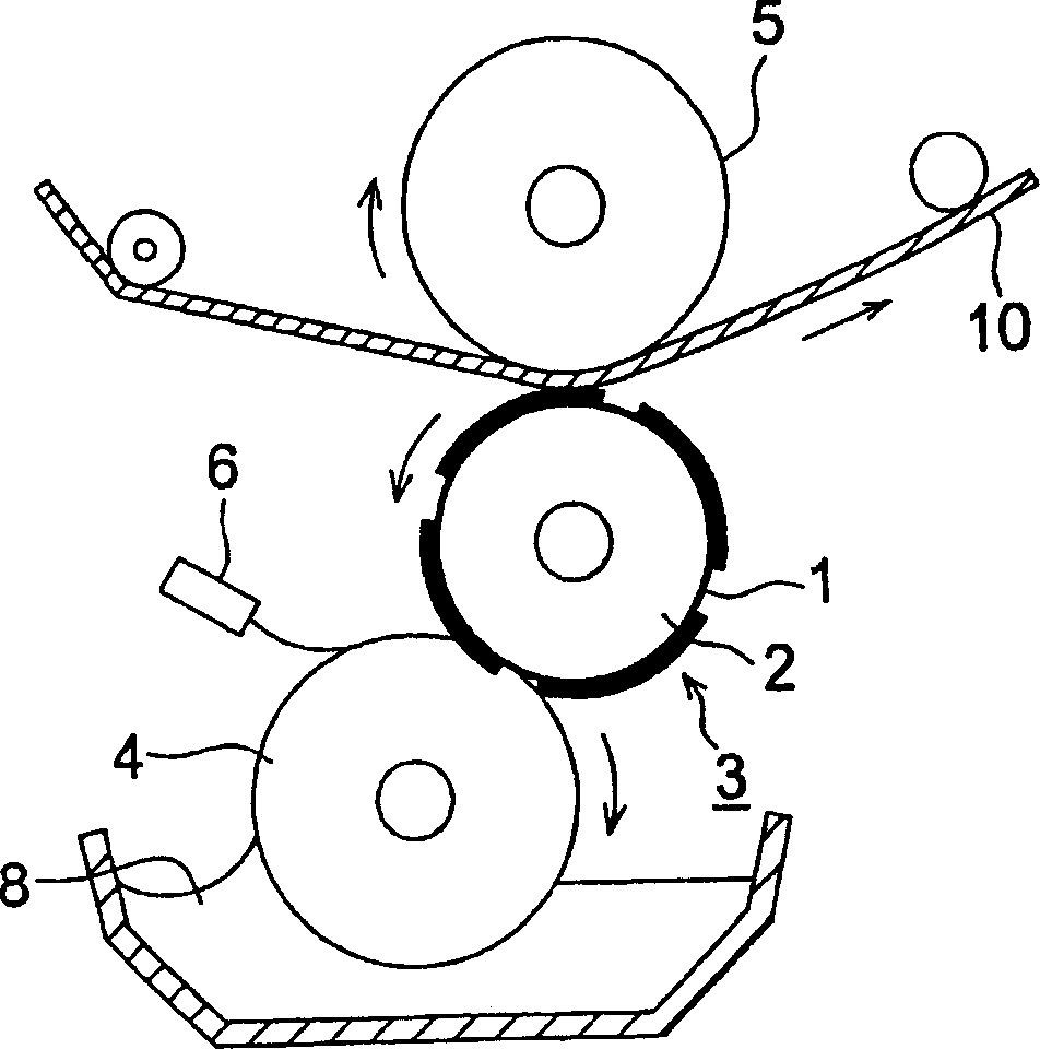
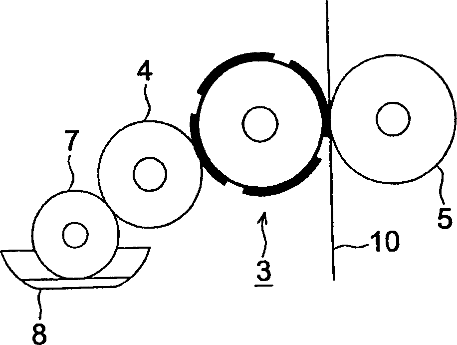
[0632]Next, instead of using Figure 8 In the manufacturing apparatus of (b), the flexographic printing part B uses the resin printing plate used in Example 1 (the diameter of the resin printing plate is 800 mm, and the rubber hardness is 50 degrees), and the flexographic printing part C uses the resin printing plate produced above, and Except the method of performing flexographic printing twice, it carried out similarly to Example 1, and produced the antiglare hard coat film. At this time, the diameter of the resin printing plate of the flexographic printing part C was 500 mm, and the rubber hardness w...

Embodiment 3

[0636] In embodiment 1, in the composition of anti-glare layer ink liquid 1, the amount of methyl ethyl ketone is adjusted to make the viscosity of ink liquid change to 0.05, 0.1, 1, 5, 8, 10, 11Pa·s, in order to prevent glare Under the conditions of the antireflection film 7, when the uneven structure was formed by flexographic printing, the viscosity of the ink liquid was in the range of 0.1 to 10 Pa·s, and it was confirmed that the desired uneven structure was formed. On the other hand, the height of the convex portion of the ink liquid of 0.05 Pa·s is reduced by 30%, and the size is increased by 40%, so it is difficult to obtain the desired concave-convex structure. In addition, it can be seen that the ink liquid of 11 Pa·s is slightly lacking in the convex portion, and the transferability of the ink is poor.


PUM

PropertyMeasurementUnit
hardnessaaaaaaaaaa
hardnessaaaaaaaaaa
thicknessaaaaaaaaaa

Abstract

The purpose of the present invention is to provide a high-definition image that does not decrease in sharpness due to miniaturization of the pixel size, and can prevent the reflection of external light and effectively prevent the decrease in contrast. An anti-glare film in which a desired fine uneven structure is stably formed and a method for producing the same, and an anti-glare antireflection film, a polarizing plate, and a display device using the anti-glare film are also provided. The method for producing the anti-glare film is characterized in that it uses a seamless resin printing plate with a diameter of 50 to 1000 mm and a rubber hardness in the range of 30 to 80 degrees, and forms an ink-adhered portion on the surface of the base material film by flexographic printing. The process of forming a concave-convex structure with ink non-adhered parts.

Description

technical field [0001] The present invention relates to an anti-glare film, a method for producing an anti-glare film, an anti-glare anti-reflection film, a polarizing plate, and a display device. Antiglare film with reduced contrast, method for producing the antiglare film, antiglare antireflection film, polarizing plate using them, and display device. Background technique [0002] In recent years, the development of thin and lightweight personal computers has been progressing. Along with this, the protective film of the polarizing plate used for display devices, such as a liquid crystal display device, is becoming thinner, and the demand for high performance is increasing. In addition, in order to improve visibility, an anti-reflection layer is provided, and in order to prevent reflections or to obtain a display performance with less glare, many electronic computers are used to make the surface rough and provide an anti-glare layer that scatters reflected light. Or a liq...

Claims


Application Information

Patent Timeline
Patent Type & Authority Applications(China)
IPC IPC(8): G02B5/02G02B1/00G02B5/30G02F1/1335
CPCY10T428/24355B41P2200/12G02B5/02Y10T428/1041C09K2323/031E02D29/0241E02D2600/20E02D2600/40
Inventor 川上壮太
Owner KONICA MINOLTA OPTO
Why Eureka
Try Eureka