Iron-core magnetic gap processing technology of inductive ballast

An inductive ballast and magnetic gap technology, applied in the direction of inductors, transformers/inductor cores, circuits, etc., can solve the problems of electrical performance deterioration of inductive ballasts, safety accidents, large electromagnetic noise, etc.

Inactive Publication Date: 2006-09-13
叶志伟 +1
View PDF0 Cites 0 Cited by
  • Summary
  • Abstract
  • Description
  • Claims
  • Application Information

AI Technical Summary

Problems solved by technology

Inductive ballasts made of such an iron core, in long-term operation, due to the effects of electromagnetic force and operating temperature, the gap between the non-ferromagnetic material sheet filled in the magnetic gap of the iron core and the magnetic gap of the i

Method used


Image

  • Iron-core magnetic gap processing technology of inductive ballast
  • Iron-core magnetic gap processing technology of inductive ballast
  • Iron-core magnetic gap processing technology of inductive ballast

Examples


Embodiment 1

[0015] see Figure 5 As shown, a magnetic ballast magnetic gap processing technology, taking the double magnetic gap circular iron core as an example, the processing procedure is as follows:

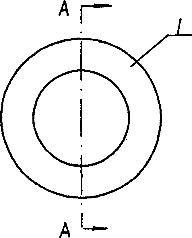
[0016] (1) A ring-shaped iron core 3 is wound into a circular iron core 3 by oriented silicon steel sheets along the paramagnetic direction, and then shaped by dipping in paint and drying.

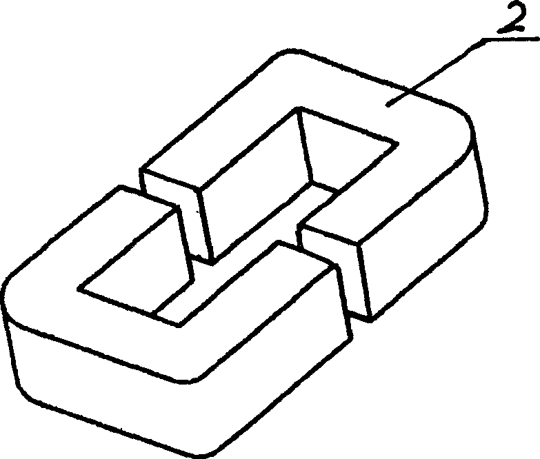
[0017] (2) Manufacture the magnetic gap: along the direction of the central axis of the ring, cut the ring-shaped iron core 3 into two half-rings 3-1, 3-2 by cutting method, and form two end faces at each cutting edge 3-1-1 and 3-2-1.

[0018] (3) Embedding magnetic gap gasket 4: use two glass fiber epoxy boards 4 with a preset thickness, respectively embedded in the magnetic gap formed by the two half-rings 3-1, 3-2, and clamp them with a clamp , forming a ring-shaped magnetic ballast core with two symmetrically arranged magnetic gaps.

[0019] (4) Stainless steel argon arc welding: The stainless...

Embodiment 2

[0024] Example 2: The iron core of the inductance ballast for the 400W metal halide lamp and the 250W high pressure sodium lamp uses two magnetic gaps, and each magnetic gap uses a stainless steel solder joint with a width of 5 mm and a depth of 2 mm.

Embodiment 3

[0025] Example 3: The iron core of an inductive ballast for a 36W fluorescent lamp uses two magnetic gaps, and each magnetic gap uses a stainless steel solder joint with a width of 3 mm and a depth of 1 mm.


PUM

PropertyMeasurementUnit
Widthaaaaaaaaaa
Radial depthaaaaaaaaaa
Widthaaaaaaaaaa

Abstract

This invention discloses an iron core magnet gap process technology of inductance ballasts, which welds dots of non-iron magnetic substance between two opposite core end faces around the gap and form alloy connections.

Description

technical field [0001] The invention relates to the technical field of inductive ballast iron core manufacturing, in particular to a magnetic gap processing technology for inductive ballast iron core. Background technique [0002] The magnetic ballast used in lighting appliances is actually a coil of iron core with a magnetic gap in a closed magnetic circuit. At present, it belongs to the magnetic ballast with a relatively new structure, and its iron core is made into various shapes to adapt to various applications, such as ring iron core 1, C-shaped iron core 2, O-shaped iron core 3, etc., see Figure 1-4 shown. But regardless of the shape, these inductive ballasts are made of oriented silicon steel sheets and wound along the paramagnetic direction, and then cut one or more magnetic gaps in the closed iron core to use Non-ferromagnetic material sheets and adhesives are used to fill the magnetic gap and bonded to the smooth core end faces on both sides of the magnetic gap. ...

Claims


Application Information

Patent Timeline
IPC IPC(8): H01F27/24H01F38/10
Inventor 叶志伟叶志祥
Owner 叶志伟
Why Eureka
Try Eureka