Fanout digit variable optical shunt

An optical splitter and fan-out technology, applied in the field of optical communication, can solve the problems of increasing the complexity and cost of the network structure, the overall loss of the optical signal, and the impact, etc. The overall effect of small loss

Inactive Publication Date: 2006-09-20
UNIV OF ELECTRONICS SCI & TECH OF CHINA
View PDF0 Cites 0 Cited by
  • Summary
  • Abstract
  • Description
  • Claims
  • Application Information

AI Technical Summary

Problems solved by technology

Since the optical splitter 2 with a constant fanout number has a fixed fanout number, the input optical signal is divided into n identical output optical signals, and ideally the power of each output optical signal is 1 / n of the input signal ; However, when the splitting number required by the input optical signal, that is, the multicast fan-out number is less than the fan-out number n of the optical splitter, it will introduce unnecessary loss, especially the multicast fan-out number is much smaller than the fan-out When the number is n, the overall loss of the optical signal is too large, so that it has to be amplified in the subsequent processing, which will affect the switching and connection of the subsequent stage, and will inevitably increase the complexity and cost of the network structure

Method used


Image

  • Fanout digit variable optical shunt
  • Fanout digit variable optical shunt
  • Fanout digit variable optical shunt

Examples


Embodiment Construction

[0018] The content of the present invention will be described below in conjunction with the accompanying drawings and specific implementation examples.

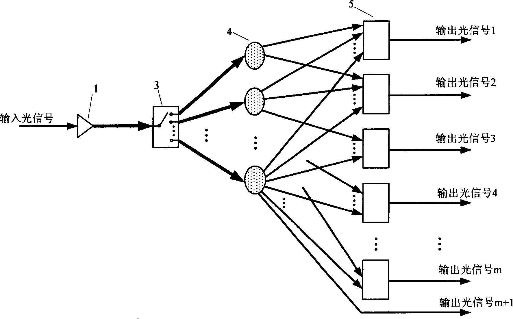
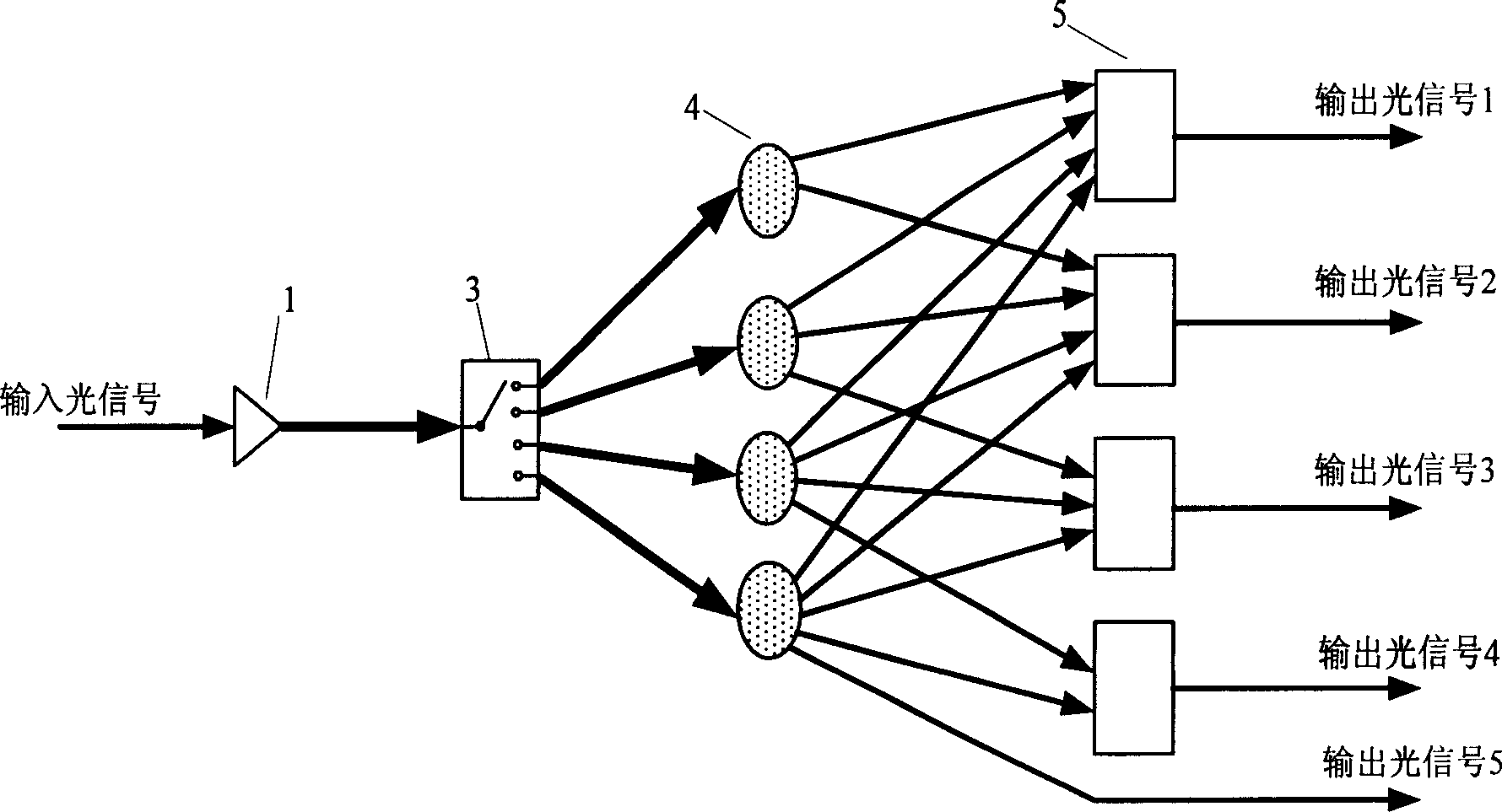
[0019] image 3 It is a structural schematic diagram of a specific embodiment of the present invention, wherein 1 is an optical amplifier, 3 is a 1×4 optical switch; 4 is a 1×n optical splitter (n=2,3,4,5); 5 is n ×1 optical multiplexer (n=4, 4, 3, 2).

[0020] Such as image 3 As shown, an optical splitter with a variable fan-out number is composed of an optical amplifier 1, a 1×4 optical switch 3, four optical splitters 4 and four optical multiplexers 5; The four optical splitters 4 are respectively a 1×2 optical splitter, a 1×3 optical splitter, a 1×4 optical splitter, and a 1×5 optical splitter; the four The optical multiplexer 5 is two 4×1 optical multiplexers, one 3×1 optical multiplexer, and one 2×1 optical multiplexer; the input optical signal is connected to the input terminal of the optical amplifier 1, and the o...


PUM


Abstract

The invention relates to an optical tapping element that the number of fan outs could be altered. It is made up of a light amplifier, a 1*m light switch, and m optical compounding elements. The input light signal passing through light amplifier and input to light switch; according to the light tapping information, the light switch would select the certain optical tapping element to take optical signal tapping; finally, the optical signal would be output. The invention could solve the consumption problem, and the optical switch would take selecting control according to the plural fan outs. It could be used in multicasting optical exchange network and broadcasting distributing network.

Description

technical field [0001] An optical splitter with variable fan-out number belongs to the technical field of optical communication, relates to an optical splitter structure, and is mainly used in a multicast optical switching network and an optical broadcast distribution network. Background technique [0002] Optical switching is an inevitable trend for the development of optical fiber communication technology in the direction of higher capacity, faster and more economical, and it is also a key technology for optical fiber transmission in the next generation network (NGN). Optical switching has experienced the development from Optical Wavelength Routing (OCS), Optical Burst Switching (OBS) to Optical Packet Switching (OPS), and many technologies have made great progress and are moving towards application. At present, the rapidly developing IP network based on optical network has become an important carrier entity for Internet TV, online games, videophone, telemedicine, distance...

Claims


Application Information

Patent Timeline
Patent Type & Authority Applications(China)
IPC IPC(8): G02B6/125
Inventor 邱琪陈宣苏廖云
Owner UNIV OF ELECTRONICS SCI & TECH OF CHINA
Why Eureka
Try Eureka