Etching method and apparatus
A technique for etching and etching films, which is used in transmission systems, electrical components, plasma, etc.
- Summary
- Abstract
- Description
- Claims
- Application Information
AI Technical Summary
Problems solved by technology
Method used
Image

Examples
Embodiment 1
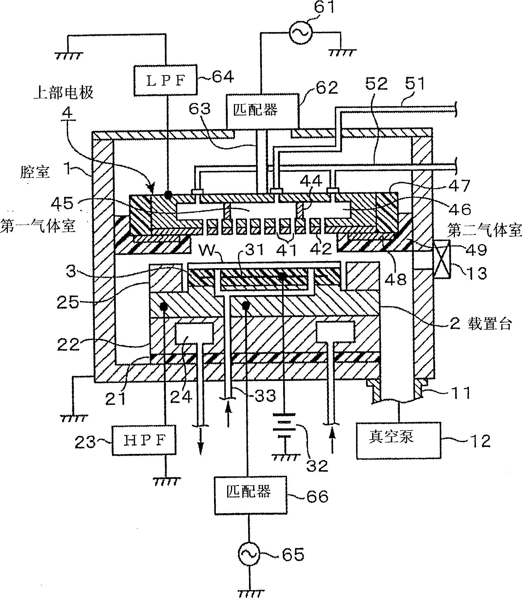
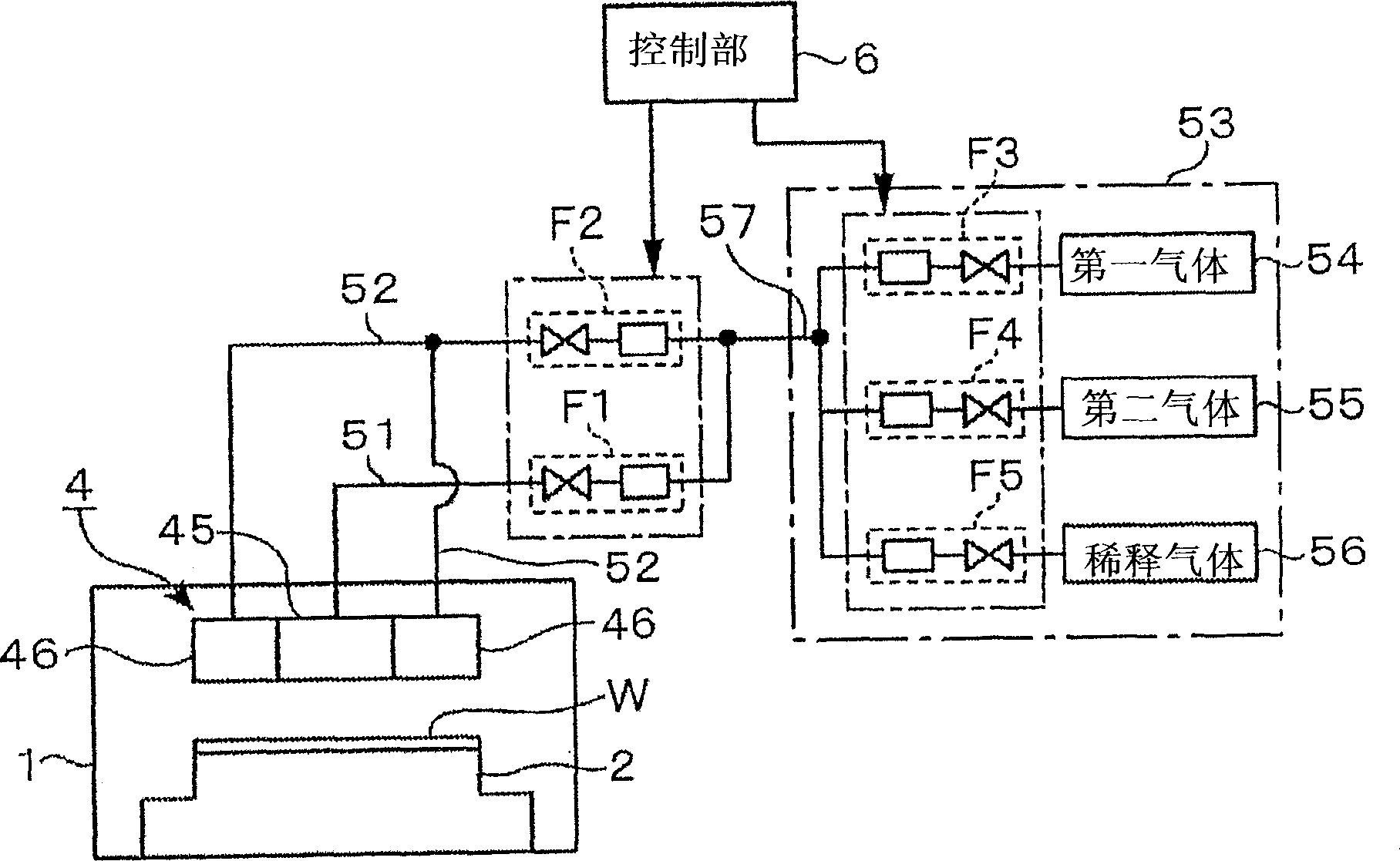
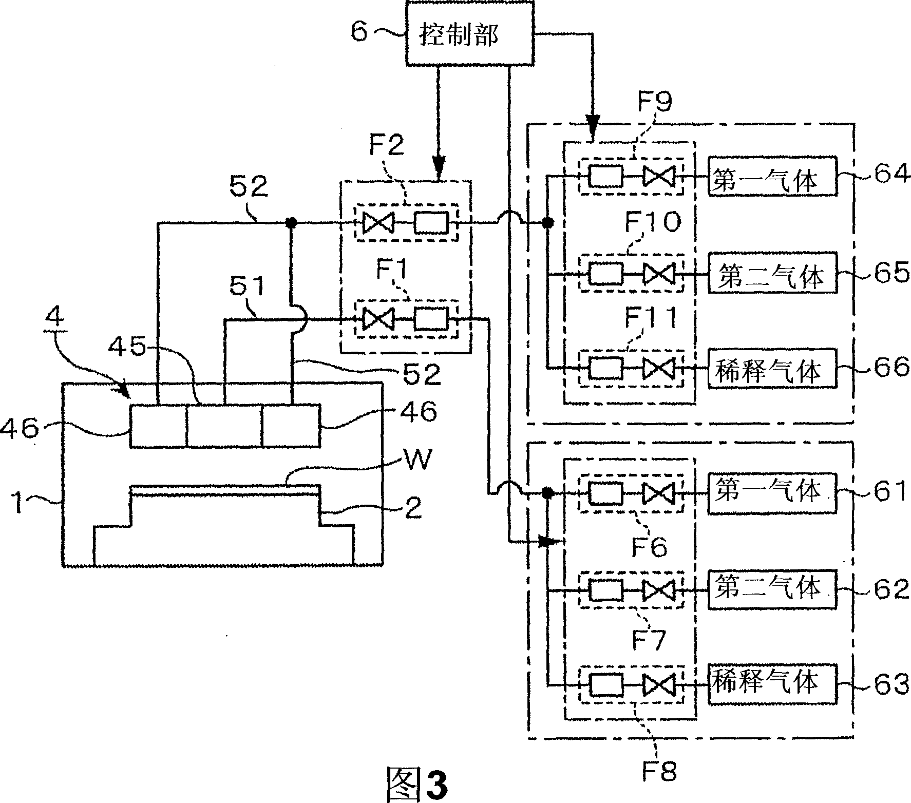
[0138] Use of CHF 3 Gas as CF gas, using Ar and N 2 The gas is used as the process gas of the diluent gas, pre-mixed, and introduced into the figure 1 In the plasma etching apparatus shown, under the following processing conditions, the supply amount to the central region of the gas supply surface and the supply amount to the peripheral region were changed, and the resist film formed on the wafer W (over the entire wafer Formed on the surface of W, no pattern is formed) for etching treatment, by the CF density at this time, CF 2 The uniformity of the density in the plane of the wafer W was measured by LIF (Laser Induced Fluorescence). Here, the above-mentioned flow rate ratio C / E of the processing gas is set to 0 / 10, 3 / 7, 5 / 5, 7 / 3, and 10 / 0. The flow rate ratio C / E being 0 / 10 means that the processing gas is supplied only to the peripheral region of the gas supply surface.
[0139]
[0140] · CHF 3 Gas, Ar gas, N 2 gas flow ratio
[0141] CHF 3 :Ar:N 2 =40:1000:80sccm...
Embodiment 2
[0149] Use of CHF 3 Gas as CF type gas, using Ar gas and N 2 The gas is used as the processing gas of the diluent gas, after pre-mixing, it is introduced into such as figure 1 In the plasma etching apparatus shown, under the following processing conditions, the flow rate of the processing gas in the central region of the gas supply surface and the flow rate in the peripheral region are changed, and the film to be etched (SiO 2 film) was etched, and the remaining resist film, etching depth, upper CD, and in-plane uniformity at the bending position were evaluated. At this time, the flow rate ratios of the gas in the central area and the peripheral area of the gas supply surface are treated as 1 / 9, 5 / 5, and 9 / 1 as the flow rate ratio C / E.
[0150] here, in Figure 8 In (a), 71 is the SiOC film as the film to be etched, 72 is the resist film formed on the surface of the SiOC film, the above-mentioned resist remaining film represents the distance A, the etching depth represent...
Embodiment 3
[0160] Use of CHF 3 The gas is CF type gas, Ar gas, N 2 Gas and O 2 The gas is pre-mixed as a process gas for diluent gas and is introduced into e.g. figure 1 In the plasma etching apparatus shown in , under the following processing conditions, the flow rate of the processing gas supplied to the central region and the peripheral region of the above-mentioned gas supply surface was changed, and the etching process was carried out on the film to be etched (SiOCH film) formed on the wafer W. In the etching process, the in-plane uniformity of the upper CD formed by etching at this time and the in-plane uniformity of the etching depth were evaluated.
[0161]
[0162] ·Processing pressure: 6.65Pa (50mTorr)
[0163] · Frequency and power of the first high-frequency power supply 61: 60MHz, 1500W
[0164] · Frequency and power of the second high-frequency power supply 65: 2MHz, 2800W
[0165] Figure 9 (a) showing the in-plane uniformity of the above upper CD, Figure 9 (b) s...
PUM
| Property | Measurement | Unit |
|---|---|---|
| Thickness | aaaaa | aaaaa |
| Thickness | aaaaa | aaaaa |
Abstract
Description
Claims
Application Information
 - Generate Ideas
- Intellectual Property
- Life Sciences
- Materials
- Tech Scout
- Unparalleled Data Quality
- Higher Quality Content
- 60% Fewer Hallucinations
Browse by: Latest US Patents, China's latest patents, Technical Efficacy Thesaurus, Application Domain, Technology Topic, Popular Technical Reports.
© 2025 PatSnap. All rights reserved.Legal|Privacy policy|Modern Slavery Act Transparency Statement|Sitemap|About US| Contact US: help@patsnap.com