Coal-fired hot blast furnace with pre-combustion hearth and smoke circulating device

A flue gas circulation and hot blast stove technology, which is applied to heating devices, lighting and heating equipment, dryers, etc., can solve the problems of low thermal efficiency, short service life of coal-fired hot blast stoves, and adaptability to polluted coal quality.

Inactive Publication Date: 2006-10-11
HARBIN INST OF TECH
View PDF0 Cites 16 Cited by
  • Summary
  • Abstract
  • Description
  • Claims
  • Application Information

AI Technical Summary

Problems solved by technology

[0003] The purpose of the present invention is to solve the problems of the existing coal-fired hot-blast stoves such as short service life, low thermal efficiency, serious pollution and poor coal quality adaptability, and propose a coal-fired hot-blast stove with a pre-combustion furnace and a flue gas circulation device. The technical solution for solving the above problems is as follows: the present invention comprises a chain grate 1, a coal bucket 3, a coal gate 4, a front arch 6, a middle arch 8, a rear arch 11, a left side wall 13, a heat exchanger 14, and a top arch 17 , right side wall 19, exhaust flue 22, steel frame 31 and rear wall 33, left side wall 13 and right side wall 19 are respectively fixed on the left and right sides of chain grate 1, and front arch 6 is fixed on left side wall 13 and the front portion between the right side wall 19, the middle arch 8 is fixed on the middle part between the left side wall 13 and the right side wall 19, and the two ends of the rear wall 33 are connected with the rear ends of the left side wall 13 and the right side wall 19 respectively. Fixedly connected, the top arch 17 is fixed on the top between the left side wall 13 and the right side wall 19, the front end of the top arch 17 is flush with the front end of the front arch 6, and the rear end of the top arch 17 is arranged between the rear wall 33. The flue 30, the upper part of the middle arch 8 is provided with a gas nozzle 9, the space surrounded by the middle arch 8, the rear wall 33, the left side wall 13 and the right side wall 19 forms an open flame combustion chamber 34, and the rear arch 11 is arranged in the open flame combustion chamber 34, the left and right ends of the rear arch 11 are fixedly c

Method used


Image

  • Coal-fired hot blast furnace with pre-combustion hearth and smoke circulating device
  • Coal-fired hot blast furnace with pre-combustion hearth and smoke circulating device
  • Coal-fired hot blast furnace with pre-combustion hearth and smoke circulating device

Examples


specific Embodiment approach 1

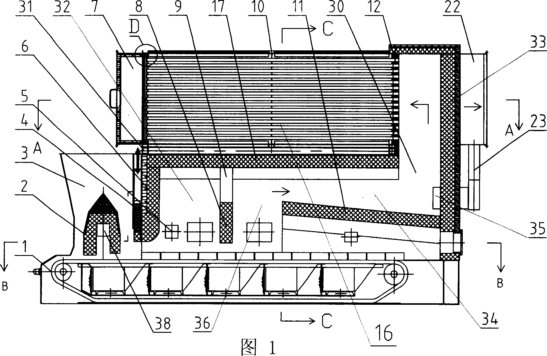
[0005] Specific embodiment one: (referring to Fig. 1~Fig. 4) this embodiment consists of chain grate 1, coal bucket 3, coal gate 4, front arch 6, middle arch 8, rear arch 11, left side wall 13, heat exchange device 14, top arch 17, right side wall 19, flue exhaust duct 22, steel frame 31, back wall 33, pre-combustion furnace 2, circulating flue 23 and circulating fan 24, left side wall 13 and right side wall 19 respectively It is fixed on the left and right sides of the chain grate 1, the front arch 6 is fixed on the front part between the left wall 13 and the right wall 19, and the middle arch 8 is fixed on the middle part between the left wall 13 and the right wall 19 , the two ends of rear wall 33 are fixedly connected with the rear ends of left side wall 13 and right side wall 19 respectively, top arch 17 is fixed on the top between left side wall 13 and right side wall 19, the front end of top arch 17 is connected with front The front end of the arch 6 is flush, a flue 30...

specific Embodiment approach 2

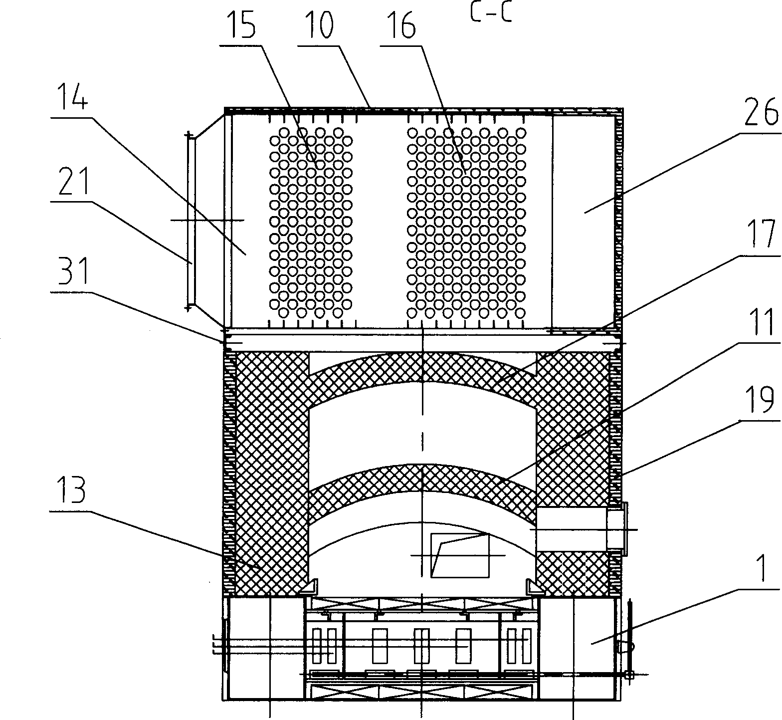
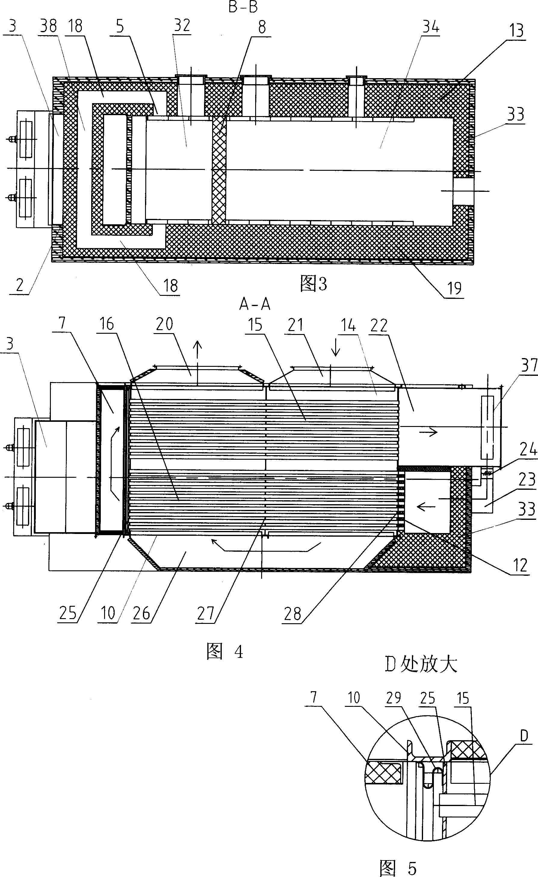
[0006] Specific implementation mode two: (referring to Fig. 1, figure 2 and Fig. 4) the heat exchanger 14 of the present embodiment is made of smoke box 7, frame 10, heat-resistant insulation layer 12, second smoke tube bundle 15, first smoke tube bundle 16, hot air outlet 20, cold air inlet 21, front tube plate 25 , turning bellows 26, middle tube plate 27 and rear tube plate 28, the rear end of smoke box 7 is fixedly connected to the front end of frame 10, the left end of turning bellows 26 is fixedly connected to the right end of frame 10, and middle tube plate 27 is fixed In the middle part of the frame 10, the rear tube plate 28 is fixed on the rear part in the frame 10, the front tube plate 25 is arranged on the front part in the frame 10, and the two ends of the second smoke tube bundle 15 are respectively fixed on the front tube plate 25 and the rear tube plate 25. On the left side of the tube plate 28, the middle part of the second smoke tube bundle 15 is fixed on the...

specific Embodiment approach 3

[0007] Embodiment 3: (see FIG. 1 and FIG. 5 ) The difference between this embodiment and Embodiment 2 is that an expansion joint 29 is provided between the front tube plate 25 of the heat exchanger 14 and the inner wall of the frame 10 . Other compositions and connections are the same as those in the second embodiment. The heat exchanger uses expansion joints to compensate for the expansion of the heated components, which avoids damage to the heat exchanger device due to thermal stress caused by thermal expansion.


PUM


Abstract

The invention discloses a coal air heater with a preignition hearth and a smoke recycler, which can solve the problems of present product with short service life, lower heating efficiency and worse environment pollution. Wherein, the wind inlet of cycle fan (24) via the cycle smoke channel (23) is through to the side opening (37) of smoke outlet channel (22)); the wind outlet of cycle fan (24) via the outlet (35) of cycle smoke channel (23) is through to the smoke channel (30); the preignition hearth (2) is fixed on the lower pat of coal hopper (3) between the left and right side walls (13). The inventive preignition hearth is thermal-insulated, with higher burning strength, and high application to variable coals. At the back of furnace row, the burnt coke can make the fire bed in open fire condition, to burn the gas fully; said air heater can avoid black smoke to reduce environment pollution; the cycle smoke channel can reduce the temperature of heat exchanger, to improve the service life and efficiency of air heater.

Description

technical field [0001] The invention relates to a coal-fired hot blast stove. Background technique [0002] The hot air stove is a device that uses the heat generated by fuel combustion to heat the air and produce hot air. It can continuously provide constant temperature, clean hot air without pollution. Most of the existing hot blast stoves use loose coal as fuel, and conventional fixed grates, chain grates or reciprocating grates are used. The initial fuel combustion of hot blast stoves is insufficient, and the concentration of smoke and dust is high, which seriously pollutes the environment. When the coal quality is poor, there will also be problems such as flame pulling, high carbon content in ash, and insufficient output of hot blast stoves. Existing hot blast stoves mostly realize heat exchange between flue gas and air through heat exchangers. Air flows on one side of the heating surface of the hot blast stove. The heat release coefficient of the air to the heating s...

Claims


Application Information

Patent Timeline
IPC IPC(8): F26B23/10F26B23/02
Inventor 赵广播周洪富黄怡珉
Owner HARBIN INST OF TECH
Why Eureka
Try Eureka