Method for decreasing thermal capacitance laser medium thermal stress

A laser medium and thermal stress technology, which is applied in the direction of lasers, laser components, laser components, etc., can solve the problems affecting the increase of laser medium output power, large thermal stress, and affecting the quality of output laser beams, etc., to achieve operability The effect of high stability, thermal stress reduction, and simple control

Inactive Publication Date: 2006-10-11
SHANGHAI INST OF OPTICS & FINE MECHANICS CHINESE ACAD OF SCI
View PDF2 Cites 3 Cited by
  • Summary
  • Abstract
  • Description
  • Claims
  • Application Information

AI Technical Summary

Problems solved by technology

However, in the actual working process, due to the existence of pumping area (effective light aperture) and non-pumping area in the laser medium, as well as the uneven distribution of pumping light, it will be inside the medium, especially in the optical aperture The edge

Method used


Image

  • Method for decreasing thermal capacitance laser medium thermal stress
  • Method for decreasing thermal capacitance laser medium thermal stress
  • Method for decreasing thermal capacitance laser medium thermal stress

Examples


Embodiment Construction

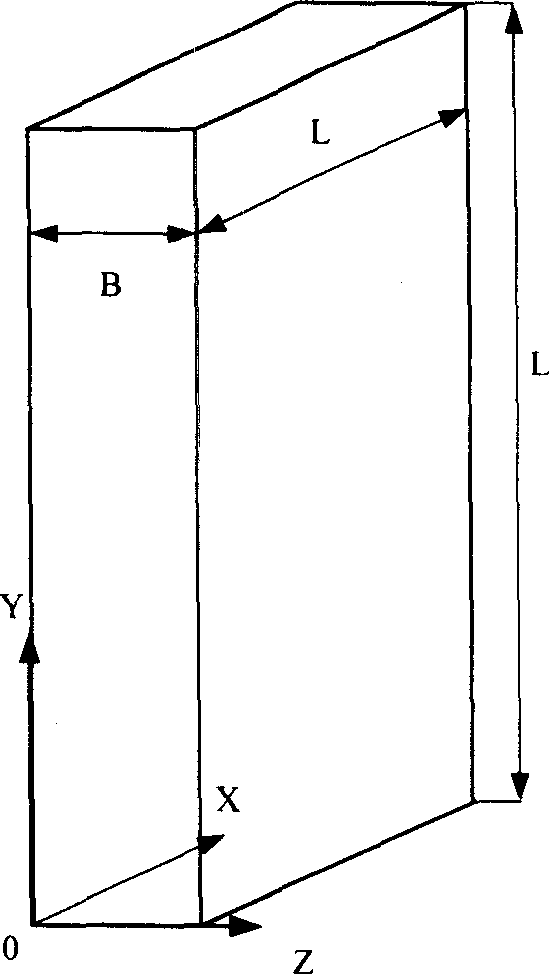
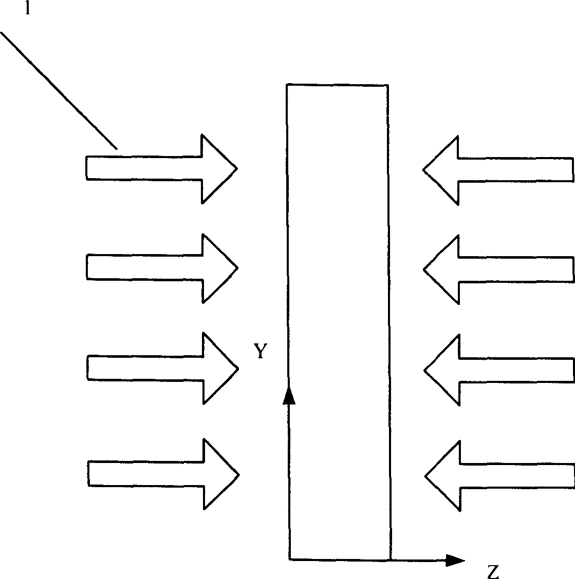
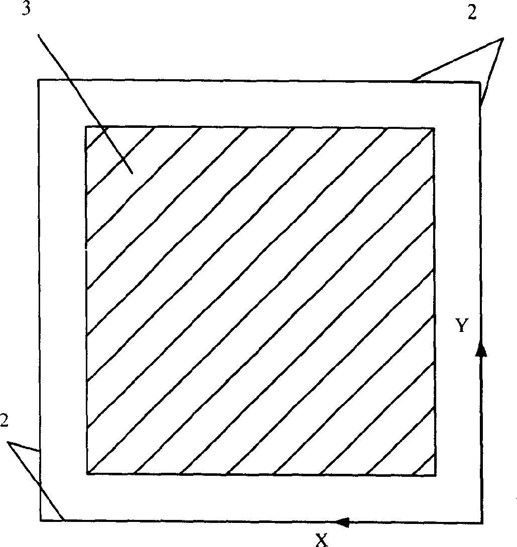
[0030] In a Nd:GGG slab heat capacity laser with double-sided symmetrical uniform pumping, the designed output power is 5KW. There are three dielectric slats in the cavity, and the geometric shape of each slat is as follows: figure 1 , the size is L×L×B=0.06×0.06×0.015m 3 , the laser emission time is designed to be 10s, and the pumping intensity is 1.160MW / m 2 , the initial ambient temperature is 293K. exist figure 2 , image 3 Among them, the uniform pumping light 1 is incident on the two pumping surfaces 3 of the laser medium, the non-pumping surface 2 is insulated, and the area of ​​the pumping surface 3’s light aperture (shaded part) is 0.05×0.05m 2 , the surface of the medium is assumed to be in an adiabatic state. After ANSYS simulation, after 10 seconds of laser emission, the maximum equivalent stress in the slab is 80MPa, which occurs at point (x, y, z: m 3 ): (0, 0.03, 0.0075), (0.03, 0.06, 0.075), (0.06, 0.03, 0.0075), (0.03, 0, 0.0075) four points.

[0031] e...


PUM


Abstract

The disclosed method to reduce the thermal stress of thermal-capacity laser medium comprises: during laser emitting, heating the un-pumping area of laser medium to decrease the temperature difference to pumping area and thereby reduce thermal stress.

Description

technical field [0001] The invention belongs to the technical field of solid-state lasers, in particular to a method for reducing thermal stress of a heat capacity laser medium. Background technique [0002] Compared with other types of lasers, solid-state lasers pumped by semiconductor lasers have output characteristics such as multi-wavelength, short-wavelength, tunable, short-pulse, and high repetition rate. They are widely used in defense industry, industrial processing, aerospace, medical and other fields. application prospects. [0003] For a long time, solid-state lasers ( S solid S tate L Aser, referred to as SSL) output power has been restricted by waste heat generated during work, it is difficult to obtain a high average power output. Although the laser diode (LD)-pumped solid-state laser (DPSSL) improves the light-to-light conversion efficiency and effectively reduces the generation of waste heat, most SSL systems still need real-time cooling during operation,...

Claims


Application Information

Patent Timeline
IPC IPC(8): H01S3/042H01S3/02
Inventor 董玥祖继锋侯立群朱健强
Owner SHANGHAI INST OF OPTICS & FINE MECHANICS CHINESE ACAD OF SCI
Why Eureka
Try Eureka